...
Using the node
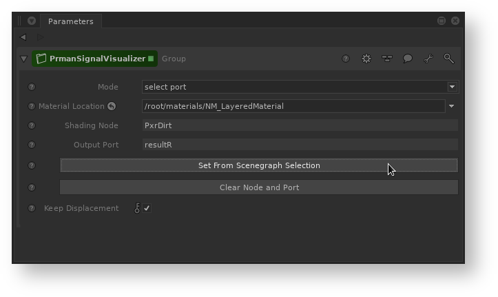
Select Port mode
- Add the node in the Node Graph downstream of where your material is created
- Select a location in the Scene Graph - a material location or a location with a local or inherited material assigned
- Press the Set from Scenegraph Selection button on PrmanSignalVisualizer
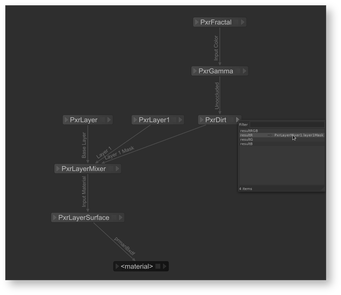
- A window will pop up and display the shading network of the material at the selected location. The nodes are automatically laid out by Katana, so the layout may not match the layout of your original material.
- In this window, choose the output of a shading node that you wish to visualize. This will populate the Material Location, Shading Node, and Output Port parameters of PrmanSignalVisualizer.
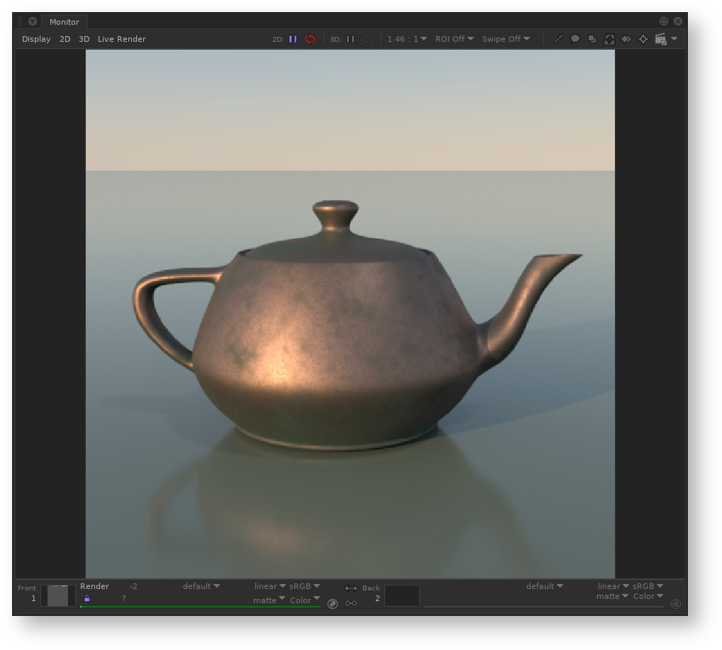
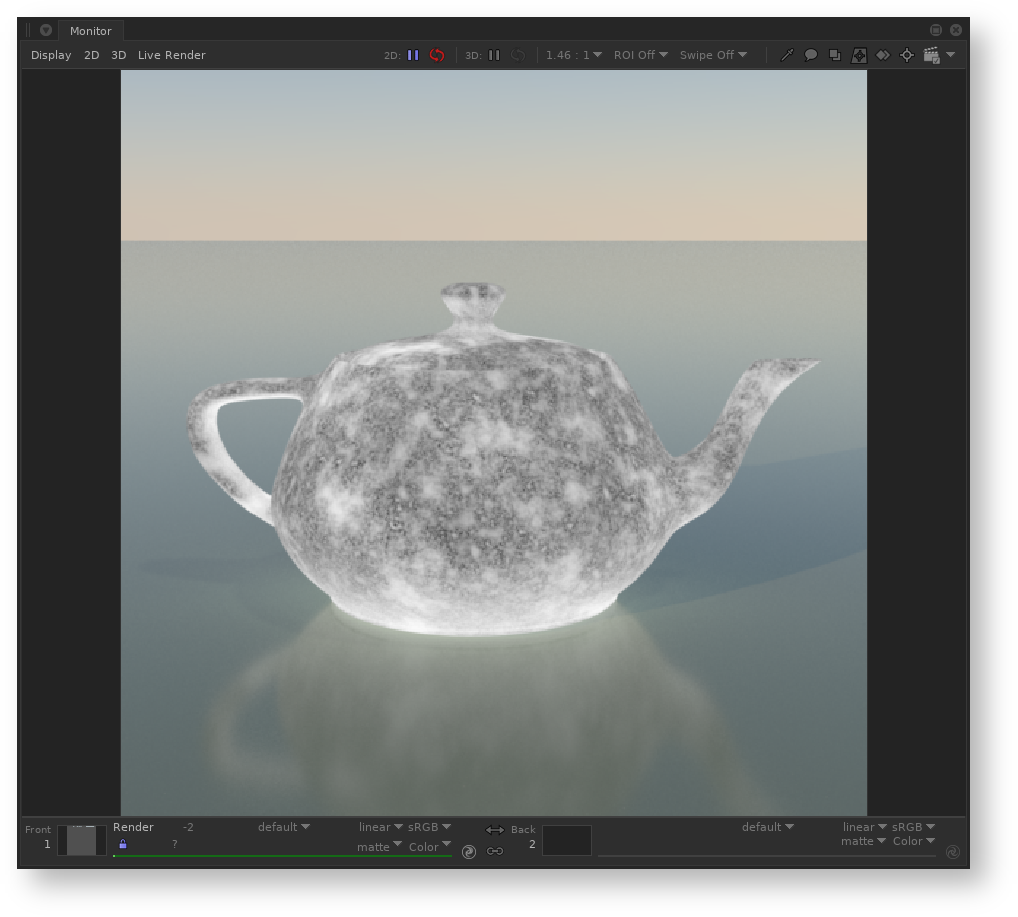
- All locations with that material assigned will now render with the isolated signal
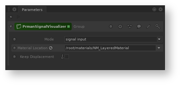
Signal Input mode
...
- Add the node in the Node Graph downstream of where your material is created. Right after the NetworkMaterial node works well for this mode.
- Wire a shading node output into the signal input of PrmanSignalVisualizerPrmanSignalVisualizer
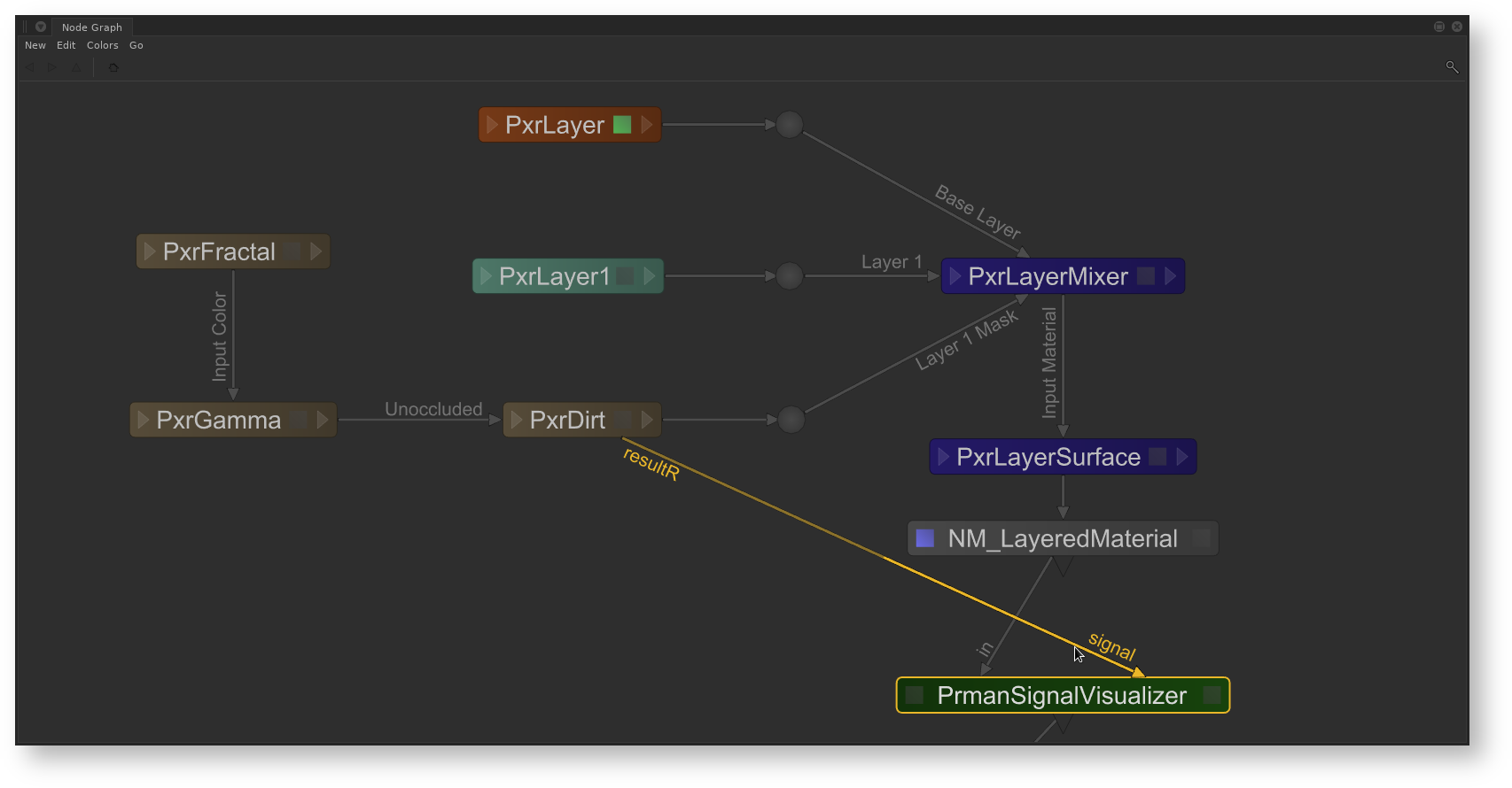
- Add the scenegraph location of the material into the Material Location parameter
- All locations with that material assigned will now render with the isolated signal
...