...
A benefit of using subdivision meshes over polygon meshes is that the topological data needed to perform subdivision is also useful for guaranteeing that the surface will remain watertight, no matter what happens in the displacement. In particular, if the faces immediately adjacent to a shared edge compute a different displacement result, on a polygon mesh a crack will likely appear as the faces pull apart. While this seems like an obvious thing to avoid, in practice it may not be easy to do so particularly when using a complicated texture asset derived from PTex or a UDIM based workflow. If a subdivision mesh is used instead of a polygon mesh, with watertight dicing enabled, the renderer can ensure that no cracks will appear at face boundaries.
| Note |
|---|
Watertight dicing can be significantly slower than regular dicing and lengthen the Time to First Pixel (TTFP). |
Boundary Interpolation
In order to provide the smoothest possible limit surface, the averaging behavior of a subdivision surface is such that the limit surface "pulls away" from the boundaries of the control mesh by default. This can be undesirable when dealing with non-closed meshes, especially those that need to connect seamlessly with other adjoining meshes. As a convenience, RenderMan provides boundary interpolation rules that allow this behavior to be overridden, allowing the surface to continue all the way to the boundary of the control mesh. Different rules allow for smooth or sharp corners (vertices which have exactly two incident edges). The example below shows the boundary interpolation rules applied to a simple 9 face control mesh.
...
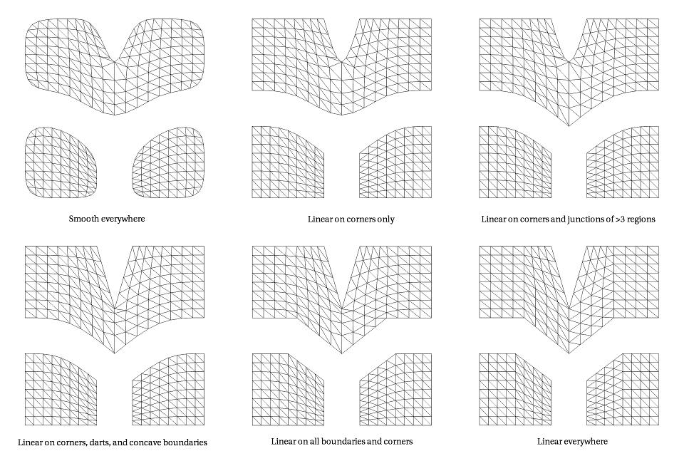
This idea of boundary interpolation can also be extended to the interpolation rules applied when dealing with data over the surface, most notably texture coordinates (in this context, RenderMan uses the term facevarying boundary interpolation). When dealing with the seams between disjoint UV regions, the renderer can use several different rules, trading off smoothness of the subdivided result away from the seams against the desire to interpolate the seams exactly. Note that no matter what rule is chosen, the UV texture map editor must also abide by the same rules, otherwise undesirable texturing artifacts will result. The following image demonstrates the different rules applied to a 4x4 grid of quads segmented into three UV regions.
The "interpolateboundary" tag controls how interpolation boundary face edges are interpolated. This tag has one optional integer argument and zero floating-point arguments. If the integer argument is not specified it is assumed to have a value of 1. A value of 0 specifies that no boundary interpolation behavior should occur (the default behavior when this tag is not specified). A value of 1 indicates that all the boundary edge-chains are sharp creases and that boundary vertices with exactly two incident edges are sharp corners. A value of 2 indicates that all the boundary edge-chains are sharp creases; boundary vertices are not affected.
| Note | ||
|---|---|---|
| ||
The "RenderMan" default is 0, however, bridge products override this to be 1. This RenderMan default may be changed in the future. Since Katana follows the RenderMan defaults, it is the sole bridge product to specify 0. |