...
TO DO: figure of 5x4 pt grid similar to figure 8.3 of ARM book. But with points P and normals Nn shown(?). Left: original surface points and normals, along with displacement amounts. Right: displaced points.
The surface positions and normals are in object space, which is convenient since the displacements scale and rotate along with the object. In the rare cases where displacements in world space are preferred, the amplitude simply needs to be scaled by the length of the normal transformed to world space. (If the master object is instanced to more than one instanced object, then the world transform of the first instance is used.)
After the displacement has been done, any smooth analytical normals that the original surface may have had (for example a smooth subdivision surface or NURBS patch) are no longer valid – they do not correspond to the displaced surface. However, each micropolygon has a geometric normal Ngn. In addition, for some surface types, a smooth shading normal will be automatically computed for each ray hit – this is done by considering the orientation of not only the micropolygon that the ray hit, but also adjacent micropolygons. (( Displaced polygon meshes deserve a special mention here. Polygon meshes do not by themselves have smooth normals, but are often defined with a normal at each polygon mesh vertex point. When a ray hits a face of an undisplaced polygon mesh, the shading normal Nn can be computed by interpolating the normals of the face vertices, leading to a smooth appearance. But for a ray hit on a displaced polygon mesh, those vertex normals are no longer valid after the displacement. A classic and very useful trick is to add back the difference between ... at ray hits on the displaced polygon mesh. WAIT A MINUTE – this trick is for bump mapping, not displacement, right?? The PxrBump shading node and RixBump() function both employ this trick. )) For other surface types – most prominently displaced polygon meshes and displaced pretessellated subdivision surfaces – the shading normal is the same as the geometric normal, i.e. facetted.
Displacement bounds
In order to ray trace a scene efficiently, RenderMan needs to know where the objects are. Objects are organized into a ray acceleration data structure: a bounding volume hierarchy (BVH) where each node in the hierarchy is a bounding box for the objects below it in the hierarchy. For displaced surfaces computing these bounding boxes is a bit tricky because we don't know where the surface points actually are until the displacement shader has run. But we don't want to run the displacement shader on all displaced surfaces before tracing the first rays – if we did, the time-to-first-pixel would suffer. What we need is a rough indication of how large the the displacement might be, without the expense of running the displacement shader to determine the exact displacement. Such an indication must be provided with a displacement bound for each displaced object; the displacement bound is an upper limit on the displacement on that object. For example, if we know that the maximum magnitude of displacement on a given object is 0.5 units, then we can specify the displacement bound like this:
...
In this example, the displacement amount computed by dispstar gets passed on to the PxrDisplace displacement shader, which does the actual displacement. Here is an image of a sphere and the same sphere with displacement (along with an image with holes due to too small displacement bound):
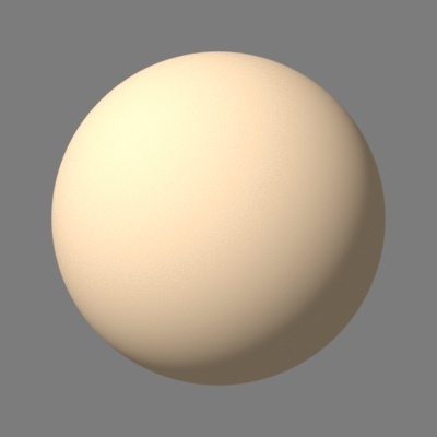

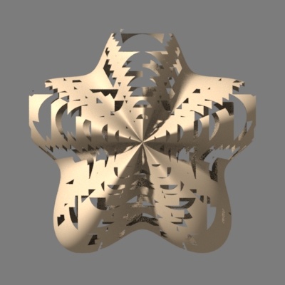
Undisplaced sphere, Left: undisplaced sphere. Middle: displaced sphere in the shape of a fat five-pointed star, and . Right: the displaced sphere with holes due to too small displacement bound.
...