...
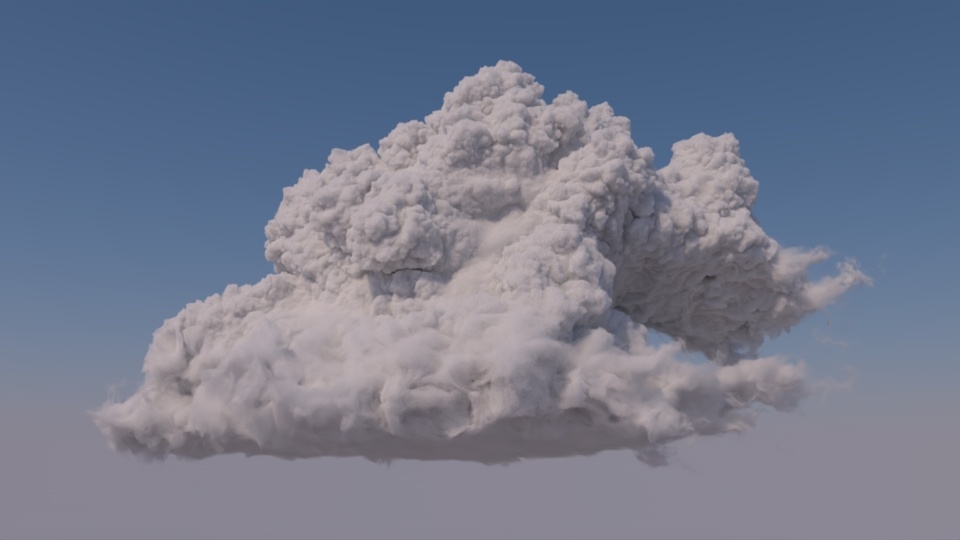
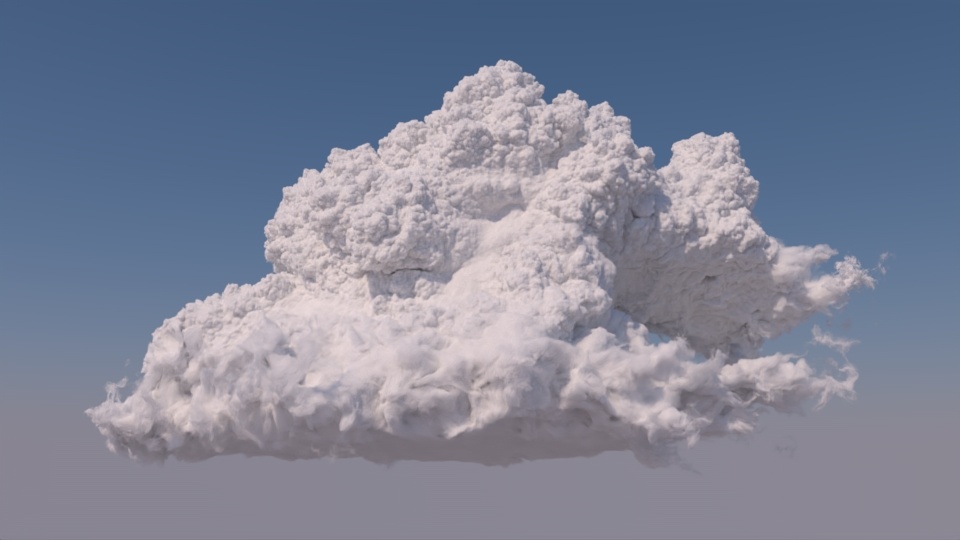
The max path length is an extremely important control when rendering clouds. A relatively high maximum path length is required to achieve a cloudlike appearance. The images below are rendered with max path lengths of 0, 16, and 64, respectively.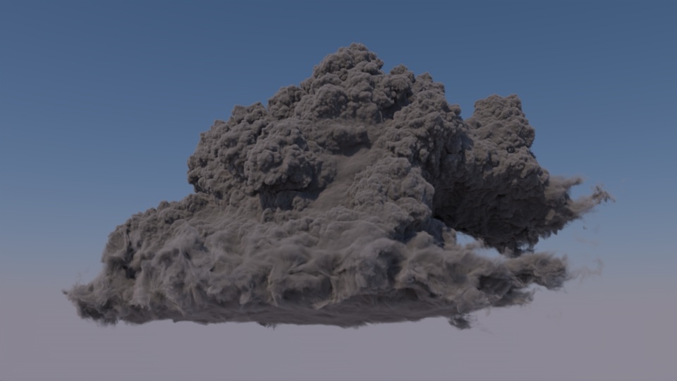

| Gallery | ||||
|---|---|---|---|---|
|
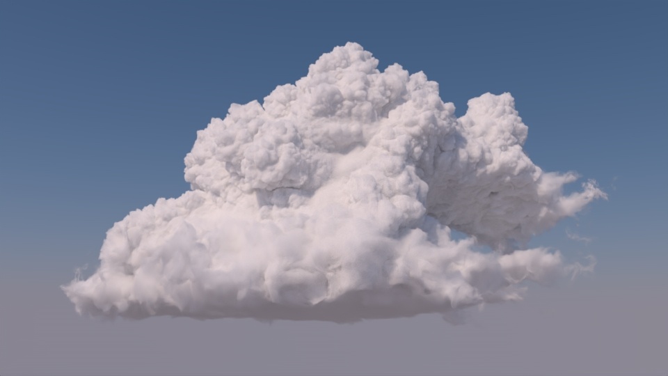
The change at higher path lengths is more subtle, but in order to get noticeable light bleed in shadowed areas of the cloud, a very high maximum path length is needed. The comparison below shows the cloud at path lengths of 64 (left) and 256 (right).
| Before After Image Slider | ||||||||||||
|---|---|---|---|---|---|---|---|---|---|---|---|---|
|
The cloud scene rendered with path lengths of 64 (left) and 256 (right).
| Tip |
|---|
Increasing the max path length also increases render times, so you should keep it as low as possible. Multi-Scattering Approximation (outlined below) can help mimic high path lengths at much lower cost. |
...
The Multi-Scattering Approx. enables or disables Multi-Scattering Approximation on a light. You should set this to 1 and adjust the Bleed and Contribution settings to achieve the desired effect. Setting this to values other than 0 (disabled) or 1 (enabled) might not produce the desired effect.
| Before After Image Slider | ||||||||||||
|---|---|---|---|---|---|---|---|---|---|---|---|---|
|
The cloud scene rendered with Multi-Scattering Approx. set to 0 (left) and 1 (right) with default Bleed and Contribution.
...
The MS Approx Bleed parameter controls how much light bleeds through a volume. Higher Bleed values allow more light to pass through the volume and light areas that would otherwise be shadowed. As such, the effect of MS Approx Bleed is most visible in shadowed areas of a volume, but it also creates a slight overall brightening effect. You can use the bleed parameter to compensate for the overall loss of brightness caused by lower Max Path Lengths.
| Before After Image Slider | ||||||||||||
|---|---|---|---|---|---|---|---|---|---|---|---|---|
|
The cloud scene rendered with Bleed set to 0.1 (left) and 0.9 (right) with default Contribution.
...
The MS Approx Contribution parameter controls how much the light bleed from the Bleed parameter contributes to the brightness of the volume. Increasing Contribution tends to increase the overall brightness of the cloud, but it brightens fringes slightly less. You can use the Contribution to help bring out detail along the edges of a volume.
| Before After Image Slider | ||||||||||||
|---|---|---|---|---|---|---|---|---|---|---|---|---|
|
The cloud scene rendered with Contribution set to 0.25 (left) and 0.75 (right) with default Bleed.
...
The density of a cloud has a significant impact on it's appearance. The main control for density is the Density Scale setting on the volume, which scales the density from the input OpenVDB file. Low Density Scale values create an airier, less detailed appearance with more light bleed, while high Density Scale values produce a thicker, more detailed, or even solid appearance.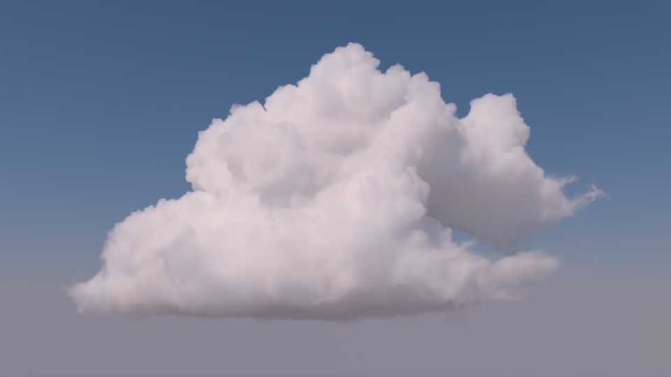
| Gallery | ||||
|---|---|---|---|---|
|
The cloud scene rendered at Density Scales of 0.2 (left), 1.0 (middle), and 5.0 (right).
...
Adjusting the anisotropy settings in PxrVolume is also critical for getting a realistic cloud render. There are three anisotropy settings to pay attention to, Primary Anisotropy, Secondary Anisotropy, and Lobe Blend Factor. The Primary and Secondary Anisotropy settings control two anisotropic lobes that can be either forward scattering (set to +1) or backward scattering (set to -1). The Lobe Blend controls the relative contribution of the two lobes, where 0 uses only the Primary lobe and 1 uses only the Secondary lobe. Setting the Primary lobe to be forward scattering flattens out detail in some areas of the cloud, but it also adds a darkening effect to parts of the cloud facing the light source.
| Before After Image Slider | ||||||||||||
|---|---|---|---|---|---|---|---|---|---|---|---|---|
|
The cloud scene rendered without anisotropy (left) and with a forward scattering Primary lobe (right) with Primary Anisotropy set to 0.8 and Blend set to 0.
Adding a backward scattering Secondary lobe recovers most of the detail lost in the forward scattering render but still retains some of the detail in the areas facing the light source.
| Before After Image Slider | ||||||||||||
|---|---|---|---|---|---|---|---|---|---|---|---|---|
|
The cloud scene rendered without anisotropy (left) and with a forward scattering Primary lobe and backward scattering Secondary lobe (right) with Primary Anisotropy set to 0.8, Secondary Anisotropy set to -0.2, and Blend set to 0.2.
...