Contents
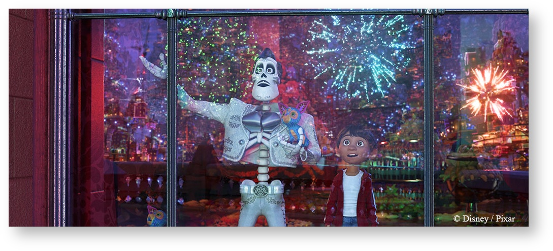
"Coco"
Rendering surfaces in RenderMan relies on a layerable material called PxrSurface.
This is the same material model used in Pixar Animation Studios' feature animation. As such there are some important benefits to this material:
- A single material handles all your looks like:
- Wood
- Skin
- Plastic
- Glass
- Car Paint
- and many many more!
- Physically based presets provided to get you started.
- Flexible controls are not required to result in something physically plausible.
- Artists can selectively "break" energy conservation.
- Art direction becomes natural without workarounds.
- Controls are conveniently labeled as "Artistic" and "Physical"
- Layering provides limitless possibilities.
As an artist, being able to choose a single material for all your shading eliminates guesswork and allows RenderMan to optimize as needed. We discuss all the different settings and their relevance to making certain materials. Pay special attention to notes about performance considerations as well as hints on what combinations will be useful for particular effects.
Below you will find each effect or lobe of the material has been separated into its own section to help users define the area they wish to learn about. However, as different lobes are activated and tweaked, the material will change looks. It's by combining these lobe settings that you can make just about any material you imagine.
Parameters begin below.
Input Material
Connect to a layer pattern that layers the parameters for the Bxdf. This lets users create more complex looks through layered effects. Examples might be dust, scratches, or even labels.
In the parameters below, some of them can be overridden by a PxrLayer when connected to the Input Material or through a PxrLayerMixer. PxrLayerSurface is designed to better illustrate which parameters are not able to be overridden in a layer by including only parameters that are global. We recommend this material when you know you will be layering. The results of these settings are unchanged.
- Bold Face parameters are layerable, able to be overridden per layer.
- Italicized parameters are not able to be layered or overridden. These are globally obeyed for all layers. For example: Choosing GGX as a specular model will mean all layers will be GGX for that parameter.
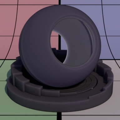
Diffuse Parameters
The diffuse parameters control the look of basic diffuse reflection. These are often used to define primary color attributes for opaque objects; wood textures, label text, polka dots, or more, you can find them all connected here. This lobe is on by default.
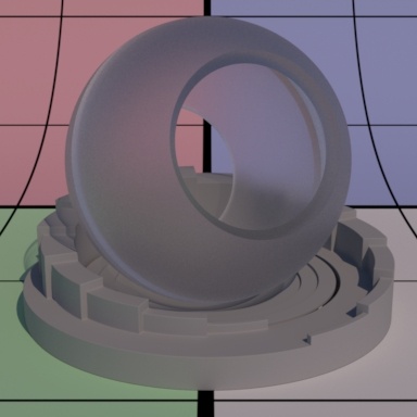
Gain
Gain is the weight applied to the diffuse parameters. You may also drive this with another pattern to show things like fading or wetness (where liquid darkens a surface). Below are examples at 0.0, 0.5, and 1.0 gain for a 50% gray material.


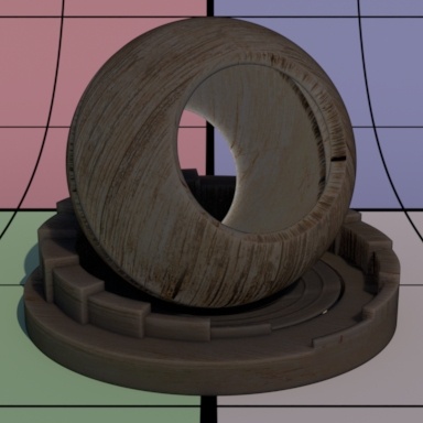
Color
Color is typically where textures or patterns are connected to create color for opaque objects. This is where a wood color texture would go, for example.
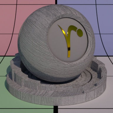
Roughness
Diffuse roughness is how you would simulate a powdery surface like dried clay or dust. When roughness is 0.0, PxrSurface uses Lambertian model to calculate the diffuse response. When roughness is > 0.0, Oren Nayar model is used instead.


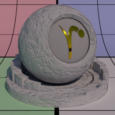
Exponent
Diffuse exponent controls the diffuse falloff. It is a power exponent. Higher number gives us sharper falloff. For example, on the moon surface, you can set a high exponent to produce a sharper falloff.
Diffuse exponent only applies to the Lambertian diffuse, that is, when roughness is 0.0. Combining diffuse exponent with Oren Nayar roughness does not make sense so it will be ignored when roughness is > 0.0.
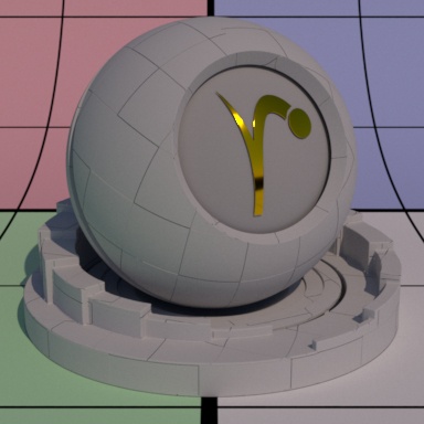
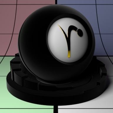
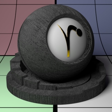
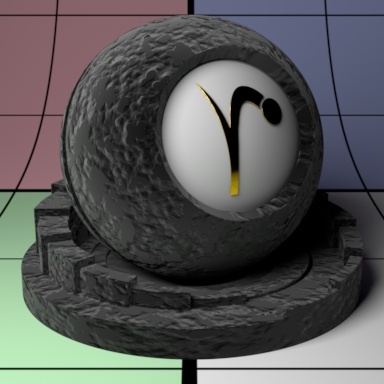
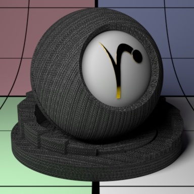
Bump
Bump mapping is a great way to fake the appearance of physical detail using shading instead. If this is not set, it will use the global bump normal specified in the Properties section near the bottom of this page.
Double Sided
If on, illuminate both sides of the surface for this diffuse lobe, that is, this will illuminate the surface whose normal is pointing away from the camera (2-dimensional objects) as well. This is so the backface will be shaded instead of black. This is off by default.
Use Diffuse Color
This only applies when Double Sided is on. By default, this is on to use the Diffuse Color for the back color.
Back Color
This only applies when Double Sided is on. When Use Diffuse Color if off, this sets the back color (the color for the back side). By default, it uses the Diffuse Color but choosing a different color provides you with a way to make the backside of 2D objects appear differently.
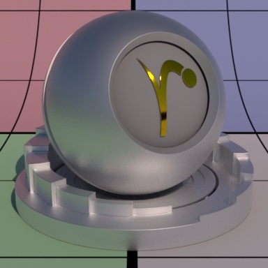
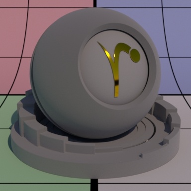
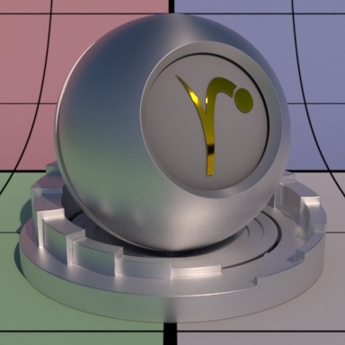
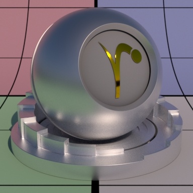
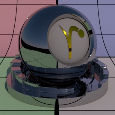
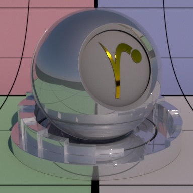
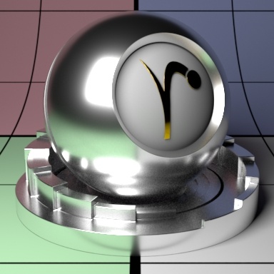
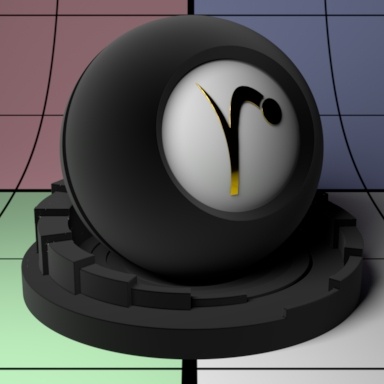
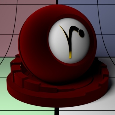
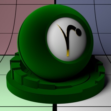
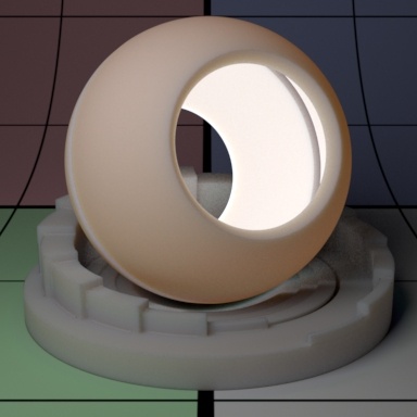
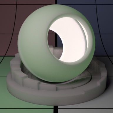
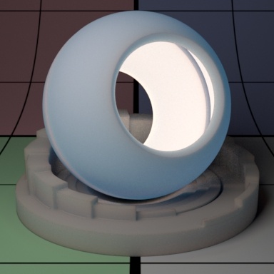
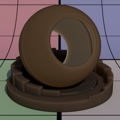
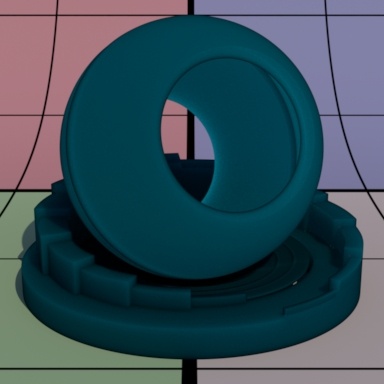
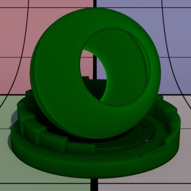
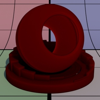
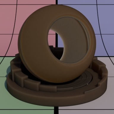
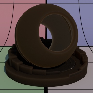
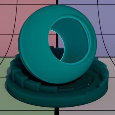
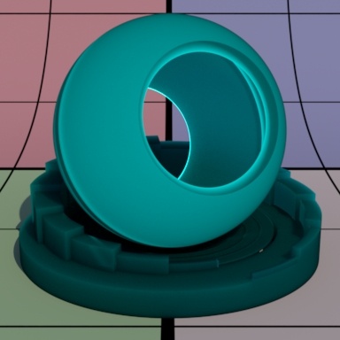
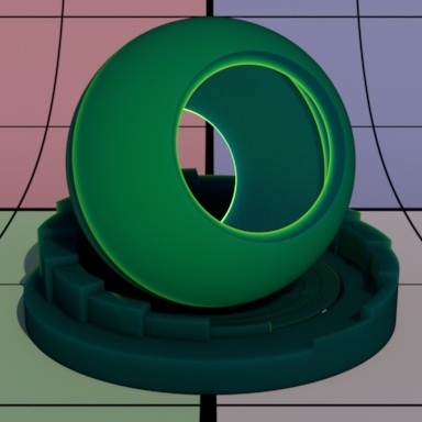
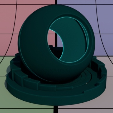
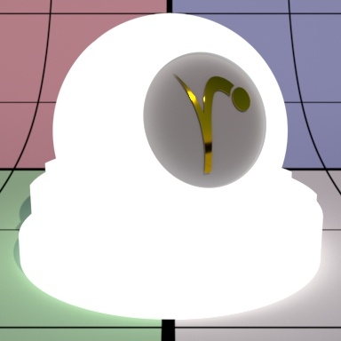
Transmit Gain
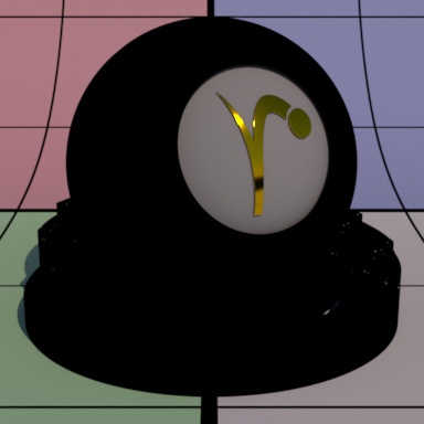
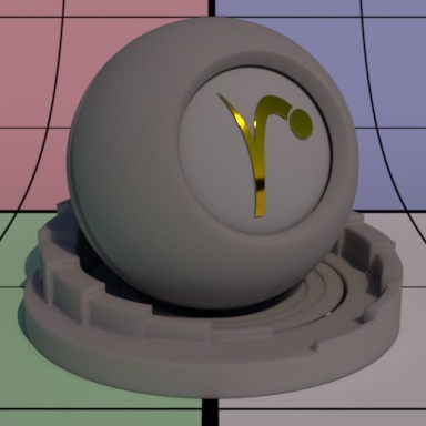
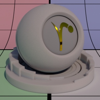
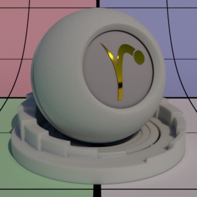
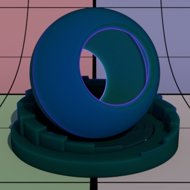
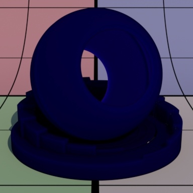
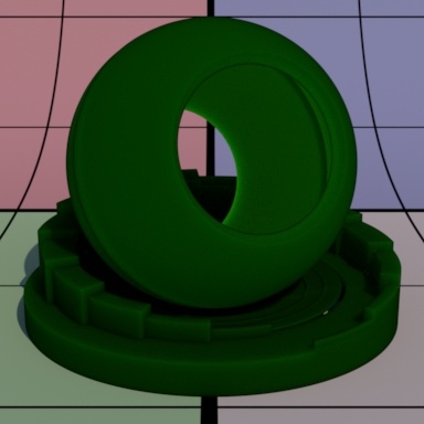
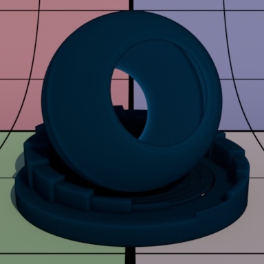
This only applies when Double Sided is on. Instead of using the Diffuse Gain for controlling the intensity of the diffuse transmission, we use the Transmit Gain. If it's 0.0, then the effect is off. Below the Transmit Color is bright blue.
![]()
![]()
![]()
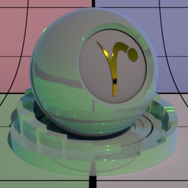
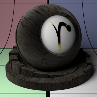
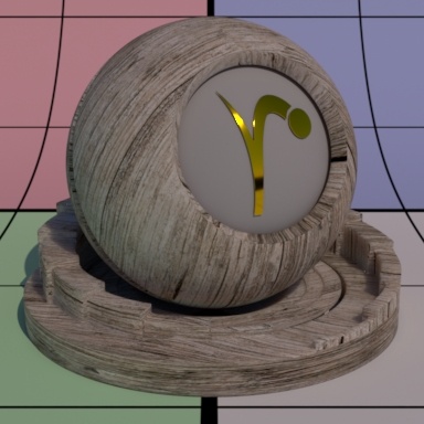
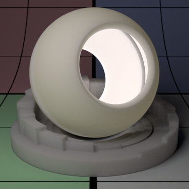
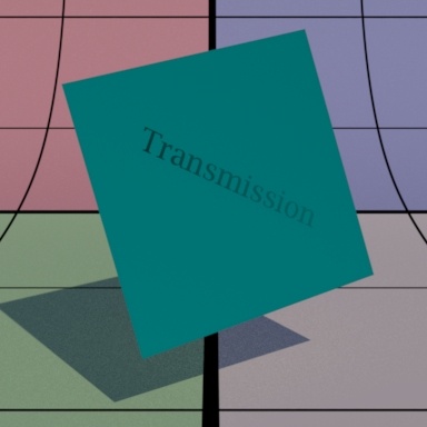
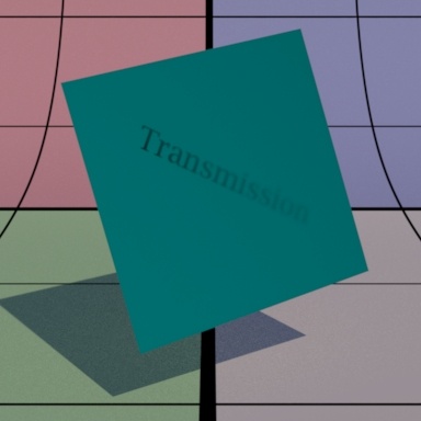
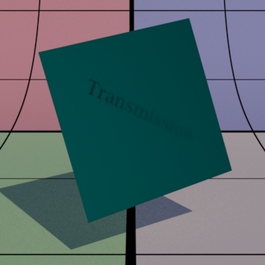
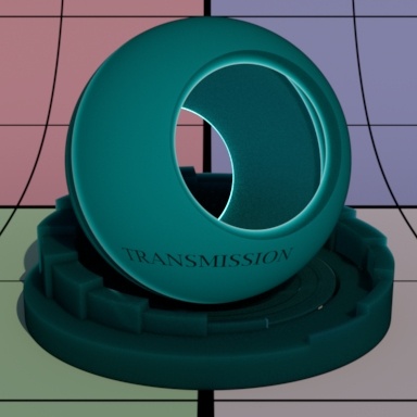
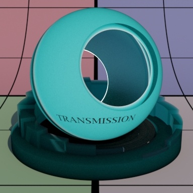
Transmit Color
This only applies when Double Sided is on. This sets the transmit color which could be different than the diffuse or back color. This is ignored if Transmit Gain is zero. This effect is useful for thin objects like leaves or paper. Below there's a light placed in the interior of the object and some interior text can be seen as light transmits through the surface.
![]()
![]()
![]()
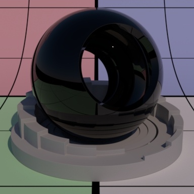
Specular and Rough Specular Parameters
The specular parameters control specular reflection. This is where you might define how shiny or reflective an object is. Is it plastic, a polished marble table, or is it a mirror? The Rough Specular lobe below this has identical settings and effects.
There's also the option for Artistic and Physical controls. The Artistic controls allows you to manually alter the properties of the reflection to match your tastes. Using Physical (with provided presets) can provide you with a matching real-world response for those looking to duplicate reality without endless tweaking.
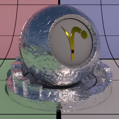
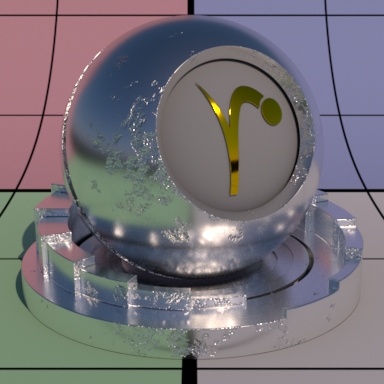
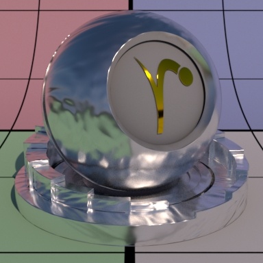
Specular Model
Select which specular model to use: Beckmann or Ggx. Beckmann is useful for perfect mirrors and chrome-like materials. Ggx may be preferred for its "tail", or how the highlight has a soft fade from the center reflection of a lightsource. Left is Beckmann and Right is GGX with roughness 0.25.
Specular Fresnel Mode
InArtisticmode, specular fresnel response will be controlled by its Face Color, Edge Color, and Fresnel Exponent.
InPhysicalmode, specular fresnel response will be controlled by its Refractive Index, Extinction Coefficient, and Edge Color.
Face Color (Artistic Mode)
Specular color at facing angle (0 degree incidence). Note that there is no separate gain control. To control the specular "gain", simply adjust the color value or connect it to a PxrExposure node. Below are different choices including textured at roughness 0.25.

Edge Color
Specular color at the glancing angle (90-degree incidence). To control the edge specular "gain", simply adjust the color value or connect it to a PxrExposure node. Below are different choices including textured at roughness 0.25. The Fresnel Exponent is also reduced here to make it more obvious.

Understand that this control changes meaning in the Physical Mode and operates as a multiplier for the reflection result in Physical mode. You can control reflection intensity and even tint the result using this parameter in Physical Mode. Below we used black, 50% gray, and white.

Fresnel Exponent (Artistic Mode)
Specular fresnel curve exponent. Lower numbers reducesthe effect of Face Color while increasing the effect of Edge Color. Higher numbers reverse this. If your face and edge colors are the same, then there is no visible effect. Below we use a red Face Color and green Edge Color and increase the Fresnel Exponent from 0.1 to 1.5 and finally 5.0 with a small roughness.
Refractive Index (Physical Mode)
This is a parameter meant to describe a physical refractive Index; the dielectric index of refraction for the material. Channel values for this parameter typically lie in the range 1 - 3. Since we support 3 color values to capture the spectral effect presets may be preferred over color pickers to avoid lots of tweaking.
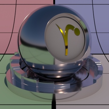
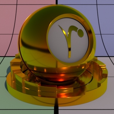
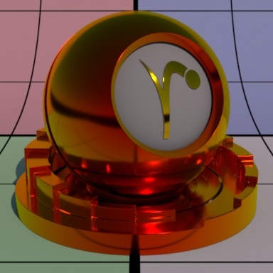
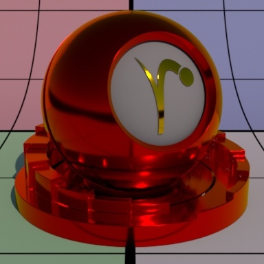
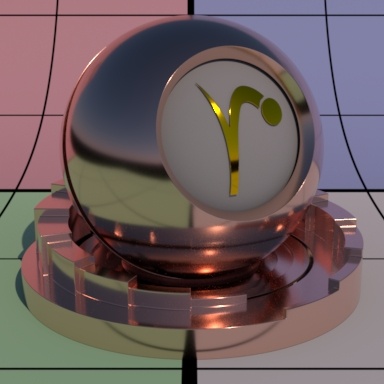
Extinction Coefficient (Physical Mode)
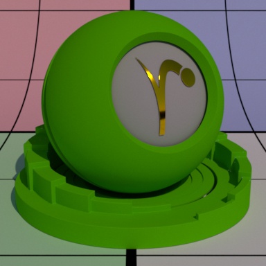
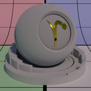
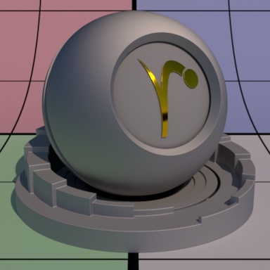
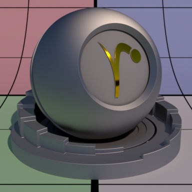
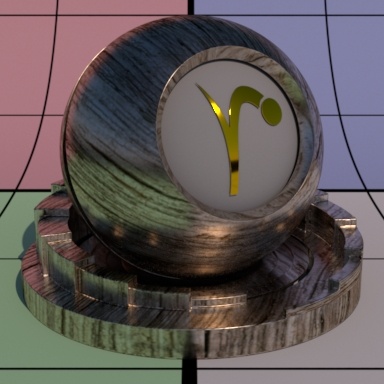
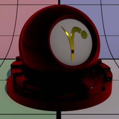
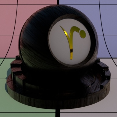
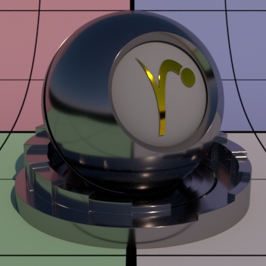
Extinction Coefficient is a second refractive index for the material useful for characterizing metallic behaviors. Channel values for this parameter typically lie in the range 1 - 3. Since we support 3 color values to capture the spectral effect presets may be preferred over color pickers. When 0, the material reacts as a dielectric (glass, clearcoat). When non-zero, the material responds as a conductor would. Since this is based on physical values you should the presets more helpful than manual tweaking of settings. Below are presets for Copper, Gold, and Nickel.
Roughness
Specular roughness. A greater value produces rougher or "blurry" specular reflection. At 1.0 it resembles a diffuse surface and at 0.0 it's a perfectly clear reflection. Most objects will be realistic somewhere in between these values. Texturing this value may give you interesting effects like smudges, greasy fingerprints, and worn surfaces. Below are examples from 0.0 to 0.5 and finally 1.0 (diffuse).
Anisotropy
Controls the shape of the specular highlights and reflections. 0 means isotropic which produces the regular circular specular highlight. Values from -1.0 to 1.0 produce the range of ellipses (stretching) from wide to tall.
By default, the direction of anisotropy is controlled by the model texture parameters. If the Shading Tangent is specified, it is used instead. Below are examples of -1.0, 0.0, and 1.0.
It's recommended that the anisotropy value be set as low as possible to achieve your desired look. Extreme values (beyond -1.0 or 1.0) may generate noise that will not resolve effectively. This can be made worse with low roughness values.
Shading Tangent
Controls the anisotropy direction. Only valid when it is connected to a pattern. This is useful for making brushed metals. Below are three examples using textures and an Anisotropy of -10
Bump
Normal to use for the specular illumination. If this is not set, it will use the global bump normal specified in the Properties near the bottom of this page.
Double Sided
If on, illuminate on both sides of the surface for this specular lobe, that is, this will illuminate the surface whose normal is pointing away from the camera as well. This is off by default to improve performance.
Rough Specular
Identical Specular parameters except it has a larger default roughness which is 0.6. This layer is intended for use with higher roughness settings than the Specular lobe above. Below from left to right: Rough Specular, Specular, both lobes combined.
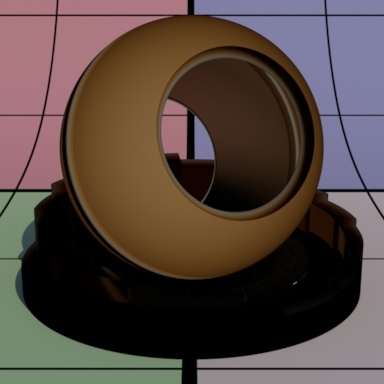
Clear Coat
Clear coats are great for making a top glazed layer found in coated objects or paints like car paint, carbon fiber, and more. You can even use a bump exclusive to this layer to make for convincing coating imperfections. While roughness is available, this layer is intended for low amounts of roughness. You will notice in the parameter examples that the base diffuse is 50% gray to illustrate how this works as a coating. If you need a metallic surface, use the above Specular lobes.
The clear coat can also be used to fake a certain thickness like a glaze on a surface using the Layer Thickness parameter.
There's also the option for Artistic and Physical controls. The Artistic controls allow you to manually alter the properties of the reflection to match your tastes. Using Physical (with provided presets) can provide you with a matching real-world response for those looking to duplicate reality without endless tweaking.
![]()
![]()
![]()
Specular Model
Select which specular model to use: Beckmann or Ggx. Again, Beckmann is useful for perfect mirrors and chrome-like materials. Ggx might be preferred for its "tail" or fade from the center highlight of reflected light sources.

Specular Fresnel Mode
InArtisticmode, specular fresnel response will be controlled by its Face Color, Edge Color, and Fresnel Exponent.
InPhysicalmode, specular fresnel response will be controlled by its Refractive Index, Extinction Coefficient, and Edge Color.
Face Color (Artistic Mode)
Specular color at facing angle (0-degree incidence). Note that there is no separate gain control. To control the specular "gain", simply adjust the color value or connect it to a PxrExposure node.
![]()
![]()
![]()
Edge Color
Specular color at the glancing angle (90-degree incidence). To control the edge specular "gain", simply adjust the color value or connect it to a PxrExposure node.
Understand that this control changes meaning in the Physical Mode and operates as a multiplier for the reflection result in Physical mode. You can control reflection intensity and even tint the result using this parameter in Physical Mode.
![]()
![]()
![]()
Fresnel Exponent (Artistic Mode)
Specular fresnel curve exponent. Lower numbers reduce the effect of Face Color while increasing the effect of Edge Color . Higher numbers reverse this. If your face and edge colors are the same, then there is no visible effect. Below we use a red Face Color and green Edge Color and increase the Fresnel Exponent from 0.1 to 1.5 and finally 5.0 with a small roughness.
![]()
![]()
![]()
Refractive Index (Physical Mode)
This is a parameter meant to describe a physical refractive Index; the dielectric index of refraction for the material. Channel values for this parameter typically lie in the range 1 - 3. Since we support 3 color values to capture the spectral effect presets may be preferred over color pickers to avoid lots of tweaking.
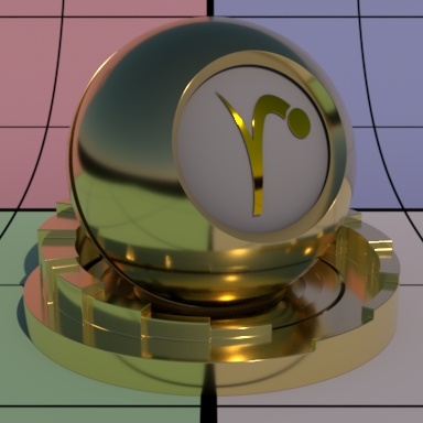
Extinction Coefficient (Physical Mode)
Extinction Coefficient is a second refractive index for the material useful for characterizing metallic behaviors. Channel values for this parameter typically lie in the range 1 - 3. Since we support 3 color values to capture the spectral effect presets may be preferred over color pickers. When 0, the material reacts as a dielectric (glass, clearcoat). When non-zero, the material responds as a conductor would. Since this is based on physical values you should find the presets more helpful than manual tweaking of settings. Left to right are Copper, Gold, and Nickel.
![]()
![]()
![]()
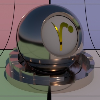
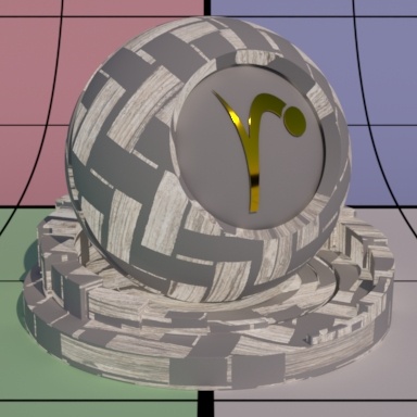
Layer Thickness (Physical Mode)
This control simulates a thick coating or glaze on the material. It can be textured to vary color as well. Below the shading ball has been given a bump on the Diffuse lobe only, making the effect of thickness more obvious for usage. The first two images are thickness 1 and 3 using the same Absorption Tint to show that thicker settings absorb more light physically. The last image is textured thickness using a checker pattern.
![]()
![]()
![]()
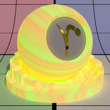
Absorption Tint (Physical Mode)
This parameter controls the color of the resulting attenuation or coating, note that the thickness parameter above may change the look, where thicker settings are more saturated or absorb more light. Below are two solid colors and then a ramp, thickness remains constant at 1.0 The underlying diffuse lobe has a bump applied to it to help simulate the "thickness".
![]()
![]()
![]()
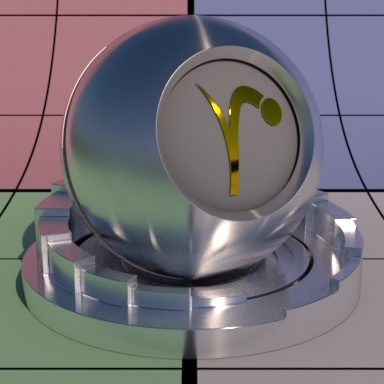
Roughness
Specular roughness. A greater value produces rougher or "blurry" specular reflection. At 1.0 it resembles a diffuse surface and at 0.0 it's a perfectly clear reflection. Most objects will be realistic somewhere in between these values. Texturing this value may give you interesting effects like smudges, greasy fingerprints, and worn surfaces. Below are values 0.0, 0.5, and 1.0
![]()
![]()
![]()
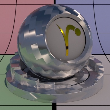
Anisotropy
Controls the shape of the specular highlights and reflections. 0 means isotropy which produces the regular circular specular highlight. Values from -1.0 to 1.0 produce the range of ellipses (stretching) from wide to tall.
By default, the direction of anisotropy is controlled by the model texture parameters. If the Shading Tangent is specified, it is used instead. You may even "overdrive" the parameter by going further than -1.0 and 1.0.
![]()
![]()
![]()
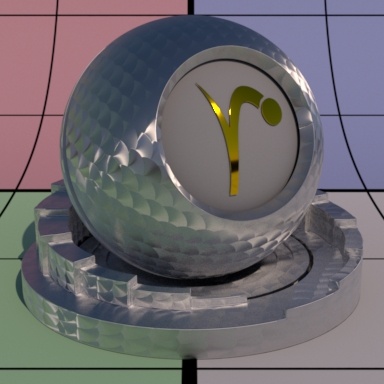
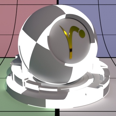
Shading Tangent
Controls the anisotropy direction. Only valid when it is connected to a pattern. This is useful for making brushed metals.
![]()
![]()
![]()
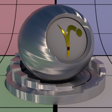
Bump
Normal to use for the clear coat illumination. If this is not set, it will use the global bump normal specified in the Properties near the bottom of the page. Setting this separately can produce a "glazed" effect where you have a bumpy clearcoat above a smooth surface.
![]()
![]()
![]()
Double Sided
If on, illuminate on both sides of the surface for this clear coat lobe, that is, this will illuminate the surface whose normal is pointing away from the camera as well.
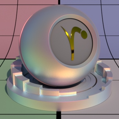
Specular Energy Compensation
Applies fresnel energy compensation to diffuse and subsurface illumination lobes. A value of 1.0 attempts to fully balance those results by darkening them against the specular and rough specular illumination responses.
Specular and Rough Specular roughness are also taken into account. The effect fades off as specular face or edge color approaches 1.0, so metals can add a diffuse baseline color. Look at Clearcoat Energy Compensation for a visual example. When Physical Fresnel mode is enabled, the energy compensation will attenuate according to ior and kappa. When Artistic mode is enabled, it will attenuate according to a curve derived from the ratio faceColor/edgeColor and is not purely physical.
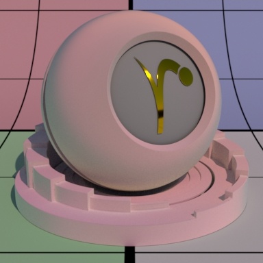
Clearcoat Energy Compensation
Applies fresnel energy compensation to all lobes other than clearcoat itself. A value of 1.0 attempts to fully balance those results by darkening them against the clearcoat illumination response.
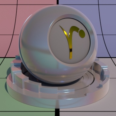
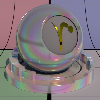
Clearcoat roughness is also taken into account. The effect fades off as clearcoat face or edge color approaches 1.0, so metals can add a diffuse baseline color. Left is 0.0 (default) Right is 1.0. Notice the darkening (changes in energy conservation) that happens.
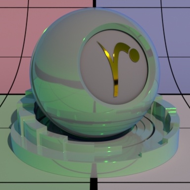
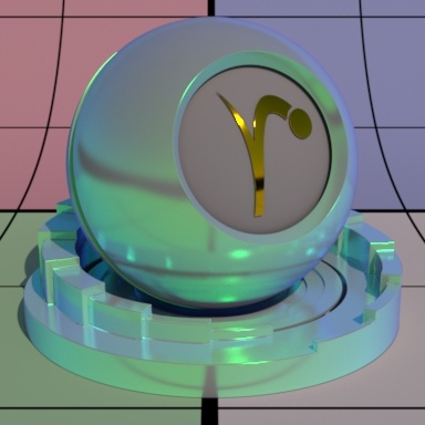
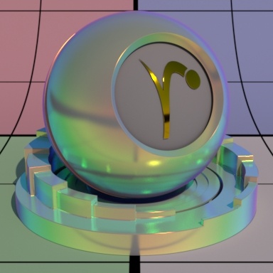
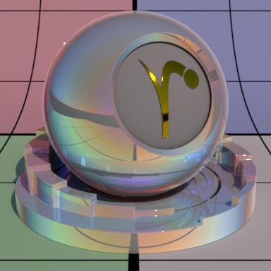
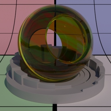
Iridescence
Iridescence is a view-dependent scattering of light that causes a color shift. This is the same effect responsible for the color swirl on a soap bubble, peacock feathers, or a shiny beetle. "Holographic" or color shifting paint uses this effect as well.
Iridescence Mode
Select which iridescence mode to use: Artistic or Physical.
In Artistic mode, we just set 2 colors. Depending on the iridescence scale factor, we will see N number of "rainbows". The default of red and blue is appropriate to get a maximum color spread but you can reduce the number of colors rendered by changing these defaults. Unless otherwise specified or demonstrating an Artistic Parameter, the examples use Physical mode.
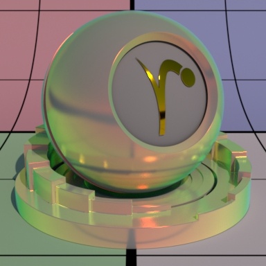
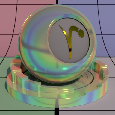
In Physical mode, we pass the thickness of your thin film in nanometers. The iridescence effect happens when the physical thickness is close to the visible spectrum. You can start around 800nm and increase the value to see the effect. This option is great because it reduces parameters to tweak at the cost of flexibility. Unless otherwise specified or demonstrating an Artistic Parameter, the examples use Physical mode. Below are Artistic (left) and Physical (right) modes.


Face Gain
Iridescence gain at facing angle (0-degree incidence).

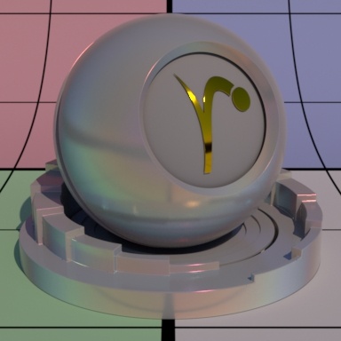
Edge Gain
Iridescence gain at the glancing angle (90-degree incidence).

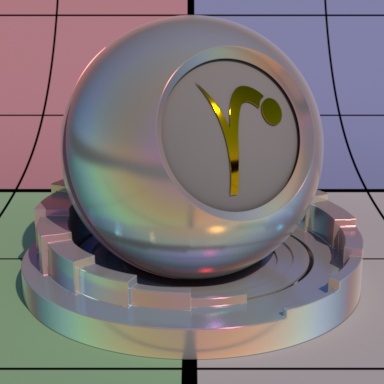
Fresnel Exponent
This controls the falloff between the face and edge. Similar to the Fresnel Exponent of the Specular Lobes. This is typically left at the default of 5.0
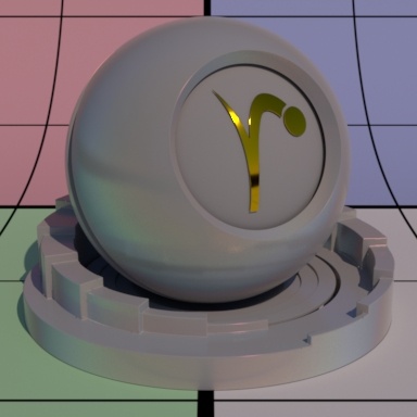
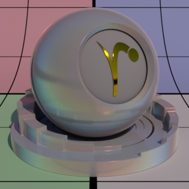
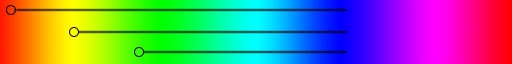
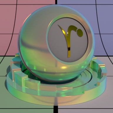
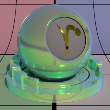
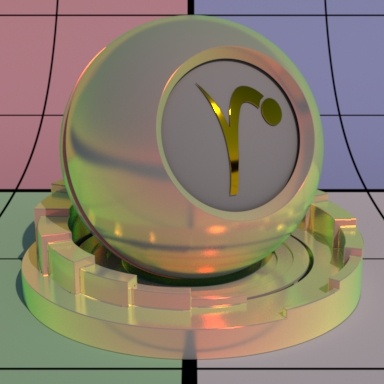
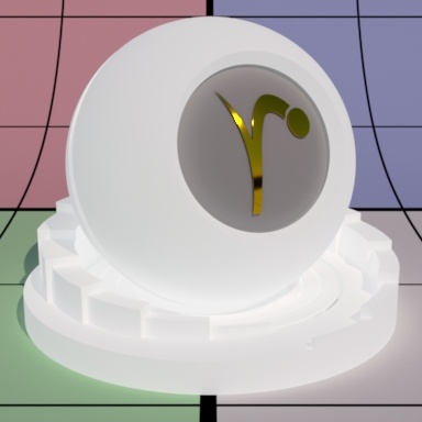
Primary Color
This is for Artistic mode only.
Iridescence primary color on the hue wheel to start from. From here the color shifts through the other available hues between the Primary and Secondary Color. The closer on the color wheel your choices, the fewer colors will be rendered. Below are three examples beginning at Red, then Yellow, and finally Green. The color bar shows what colors are available between these choices.
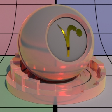
Secondary Color
This is for Artistic mode only.
Iridescence secondary color on the hue wheel to end. As demonstrated above you can use this to limit the colors rendered. Below are three examples where the Secondary Color goes from Violet to Blue and finally to Green. The hue bar shows this change on a ramp.


Falloff Speed
This is for Artistic mode only.
Falloff speed from Primary Color to Secondary Color. Larger numbers falloff more slowly. Below uses the defaults for Artistic Mode but we change the Falloff Speed from 0.1 to 0.5 to 1.0

Falloff Scale
This is for Artistic mode only.
This sets how many times the iridescence "rainbows" color repeat. Below we go from 0.5 to 1.0 and finally 3.0. Notice that higher values begin to repeat the rainbow effect. This is useful for simulating oil patterns such as oil on water or soap bubbles.


Flip Hue Direction
This is for Artistic mode only.
Flip the hue wheel direction between primary and secondary colors. By default, the hue wheel direction is counter clockwise. Left is off, right is on.


Thin Film Thickness
This is for Physical mode only.
Thinfilm thickness in nanometers. We begin at 400 then 800 and finally 1600 nanometers from left to right. Notice that at 1600 we begin to see a repetition in the rainbow effect. This is similar to the effect of using the Falloff Scale in Artistic Mode.

Roughness
Iridescence roughness, this is like other roughness parameters where you can go from a mirror-like reflection at 0.0 to diffuse reflection at 1.0. Below are examples, left to right, of 0.0, 0.5, and 1.0. Softer looks are reminiscent of color changing makeup and similar powders.
Double Sided
If on, illuminate on both sides of the surface for this iridescence lobe. This is useful forthinopened surfaces such as feathers and leaves that are modeled without thickness.
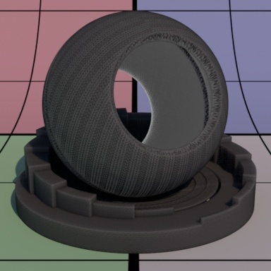
Fuzz Parameters
This parameter introduces a bit of retroreflection and helps simulate fabrics, fuzz, and fine powder.
Gain
Fuzz weight. Higher numbers increase this effect. Below the Cone Angle is set to 16.

Color
Fuzz color. This simulates a soft velvety-like effect. This is applied "on top" of the previous Specular lobes and may resemble dirt or fine dust. Below the Cone Angle is set to 16.
Cone Angle
Fuzz roughness (corresponding to Marschner R cone angle). Note that we use something from Marschner's hair model here. This helps to simulate a similar response to hair/fur. Higher numbers increase the effect at facing angles. Below are values 8, 16, and 32.


Bump
Normal to use for the fuzz illumination. If this is not set, it will use the global bump normal specified in the Properties near the bottom of this page.
Double Sided
If on, illuminate on both sides of the surface for this fuzz lobe, that is, this will illuminate the surface whose normal is pointing away from the camera as well.
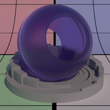
Subsurface Scattering Parameters
Note that PxrSurface supports only homogeneous volumes for these models.
Subsurface Model
Select a subsurface scattering model: Jensen Dipole, d'Eon Better Dipole, Burley Normalized, Multiple Mean Free Paths, and Path Traced Modes. The parameters are populated based on the model chosen and are valid for that model. If you change which model you use, your connections may be lost to invalid parameters.
Burley Normalized produces accurate effects while preserving details. You can find more information on the technical details of this model here .
Jensen and d'Eon Dipoles are great for very translucent objects like gummies and extended art direction.
Multiple Mean Free Paths is great for texturing to produce color bleed intuitively. While not necessarily physically correct,its scattering of textured colors works well for art direction while avoiding color shifting.
Path Traced offers two selections for brute force calculations in subsurface scattering, these provide uncompromising quality and details. The difference between the two is how light falloff is applied.
You may also find this chart helpful in choosing appropriate settings:
| Material | Albedo/Color | Mean Free Path Color |
|---|---|---|
apple | 0.846 0.841 0.528 | 6.96 6.40 1.90 |
| chicken1 | 0.314 0.156 0.126 | 11.61 3.88 1.75 |
| chicken2 | 0.321 0.160 0.108 | 9.44 3.35 1.79 |
| cream | 0.976 0.900 0.725 | 15.03 4.66 2.54 |
| ketchup | 0.164 0.006 0.002 | 4.76 0.58 0.39 |
| marble | 0.830 0.791 0.753 | 8.51 5.57 3.95 |
| potato | 0.764 0.613 0.213 | 14.27 7.23 2.04 |
| skim milk | 0.815 0.813 0.682 | 18.42 10.44 3.50 |
| skin1 | 0.436 0.227 0.131 | 3.67 1.37 0.68 |
| skin2 | 0.623 0.433 0.343 | 4.82 1.69 1.09 |
| whole milk | 0.908 0.881 0.759 | 10.90 6.58 2.51 |
Gain
Subsurface scattering weight. Higher numbers increase the visibility of the subsurface scattering.
Color
Subsurface scattering color.

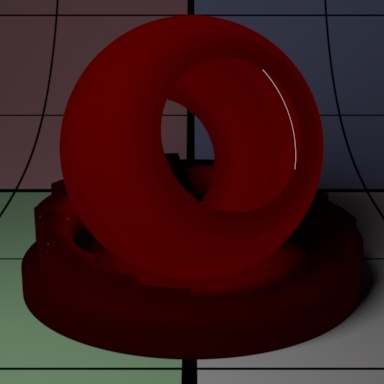
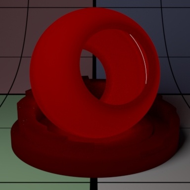
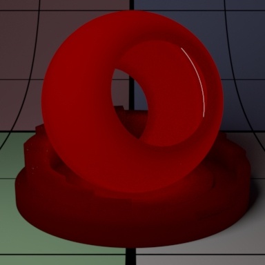
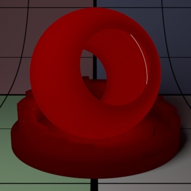
Mean Free Path Distance
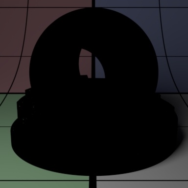
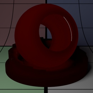
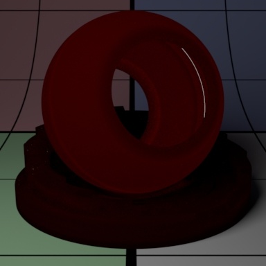
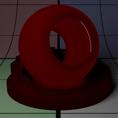
Subsurface scattering mean free path distance (mfpd). This specifies how far the light travels inside an object and as a consequence how smooth the subsurface scattering is. This gets multiplied by the unit length set in the Properties section. Higher amounts make the object appear less opaque and more translucent as well as increase noise. Small amounts make the surface look diffuse and it may be more efficient to turn off the effect (0.0 Gain) if it's not visually important. Below we change the values from 8 to 16 and then 32. Notice how the sphere and pedestal become "softer" and more translucent. Your render times might also increase at high values due to noise generated by translucent objects. Noter that high or physically implausible values may generate more noise or even fireflies in some modes.
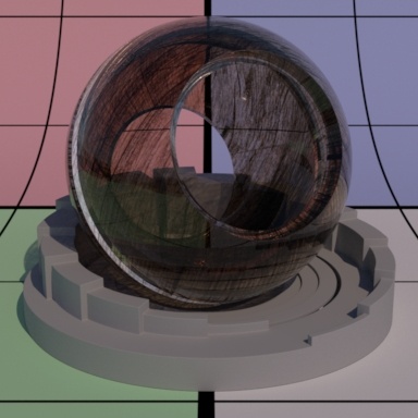
Mean Free Path Color
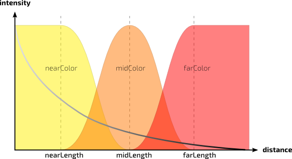
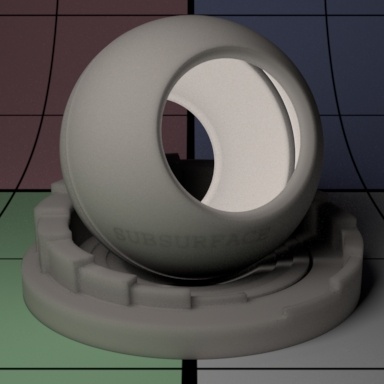
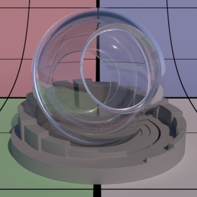
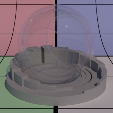
How far the light travels in the Red, Green, and Blue spectra. This is scaled by Mean Free Path Distance. Different colors may spread more or less and provide interesting effects like the red color bleeding into shadow edges on skin. The RGB values correspond to how far the light travels in that color band. For example, and RGB value of 0.8 0.65 0.5 means Red spreads furthest at 0.8, then Green and finally Blue traveling the least distance in the object scatter result. Below we've taken out the center sphere and replaced it with a bright disk light at the back of the outer sphere. Note that the sphere and pedestal share the same material and lighting plays an important role in your result.
Post Tint
Tint that is applied at the end of the subsurface computation. Below on the left is a normal render and on the right, a very light blue tint is added. If we want to apply the tint before the subsurface computation, set Irradiance Tint in the Properties section.
Path Traced (Exponential and Non-Exponential)
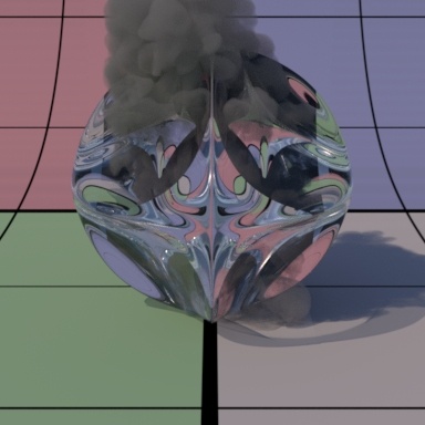
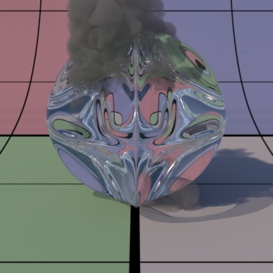
This method provides an accurate and robust light transport solution to produce scattering. This technique works well with thin geometry and edges, replacing times where you might need to combine Single and Subsurface Scattering. Note that too-large Mean Free Path settings may cause fireflies or bright spots in the resulting render.
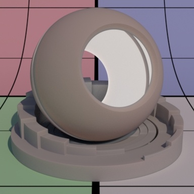
Below you see them compared, notice the Non-Exponential is brighter as light carried further into the object (examine the lower right of the spheroid model).


Directionality
This control scatters light anisotropically, that is, it can travel in one direction (forward or backwards toward the light) more than the opposite direction. In this case the light travels forward (from the light) the higher you increase the setting. Below the corners become more pronounced and the internal Subsurface geometry becomes harder to see.

Bleed
Increasing this allows the light to travel further, increasing the subsurface effect, without losing details which is typically a side effect of increasing the Diffuse Mean Free Path.
Resolve Self Intersections
If your surface has self-intersections, imagine a sock-mouth where the interior and tongue may be the same surface, only the outside is considered for subsurface scattering.
Internal Reflection Index
If you find you have some bright or "glowing" corners, you can decrease this parameter to lessen the effect. From left to right you'll notice the corners become softer and less obvious. This parameter may also be used to reduce fireflies when increased (1.0 is a soft upper limit). This may reduce the energy artificially and should be handled with care. Some over-bright areas may be caused by a large or physically incorrect Mean Free Path Distance and should be reduced rather than using this control as a first solution.


Diffuse Blend
Increasing this parameter reduces the effect of the scattering itself by blending more with a diffuse response. Notice the corners below become more "solid" looking as does the whole object.

Multiple Mean Free Paths Description
Multiple Mean Free Paths operates differently than the others in a few significant ways. For most cases, you will be happy with the results of the other models. However, there are instances where the user may want a non-physical way to control the colors of the scattering. The Mean Free Path Color in many models uses the supplied RGB value to determine the color scatter as noted in the parameter description. This means your result may have color shifts that are not desirable. Let's say you supply a textured color of RGB 0.51 0.28 0.31 which is a pink color. The scattering result will also include the green (0.28) and blue (0.31) responses. The Multiple Mean Free Paths model maintains the pink color. Below is an example using this scenario illustrating the differences. The texture is connected to the Color and Mean Free Path Color of the Jensen Dipole and to the Short and Long Colors of the Multiple Mean Free Paths model in addition. Note the color shift on the Jensen model (Left) while the Multiple Mean Free Paths version maintains the colors of the texture at all depths where connected.
Short Gain
Short subsurface gain or weight. This is only valid for Multiple Mean Free Paths subsurface model.

Short Color
Short subsurface color. This is only valid for Multiple Mean Free Paths subsurface model. Above uses Red as the chosen color.
Long Gain
Long subsurface gain or weight. This is only valid for Multiple Mean Free Paths subsurface model. Operates the same as Short Gain.
Long Color
Long subsurface color. This is only valid for Multiple Mean Free Paths subsurface model. Operates the same as Short Color.
Short MFP Distance
Short subsurfacemeanfree path scalar distance. Below we go from 16 to 24 and finally 32.
Long MFP Distance
Short subsurface meanfree path scalar distance. Below we go from 16 to 24 and finally 32.
Diffuse Computation Switch
When non-zero, it allows subsurface scattering to be approximated by simple diffuse reflection when the dmfp is shorter than the ray footprint. This gives faster rendering time and less noise -- typically on distant objects where the subsurface scattering is short relative to the size of a pixel. The default is 0 (off). Avoid using this parameter with the Path Traced options.
Double Sided
If on, illuminate on both sides of the surface for this subsurface lobe, that is, this will illuminate the surface whose normal is pointing away from the camera as well. If not on, it will not render on the backside.
Transmit Gain
This only applies when Double Sided is on. Instead of using the Subsurface Gain for controlling the intensity of the subsurface transmission, we use the Transmit Gain. If it's 0.0, then the effect is off.
Trace Control:
Consider Backside
Whether subsurface respects surfaces on the other side. This is for the hit side, not the illuminating side (which is subsurfaceDoubleSided):
- "Off" - It will ignore surfaces on the other side completely. This is useful to make objects appear thicker than they are.
- "On" - Normal mode, where the diffusion happens between the front and the first surfacebehindit.
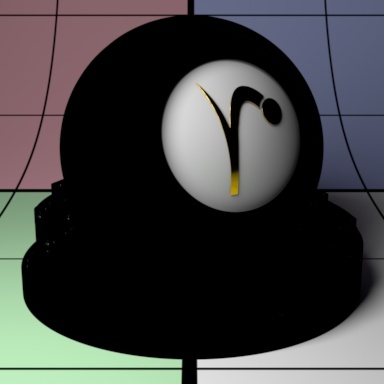
Continuation Ray Mode
This is useful when the user requires scattering to contribute between different objects as well as within an object that may be modeled with a void or space in the interior such as a mouth that is part of the same mesh as the face.
Control continuation ray mode:
"Off" - Simply trace out of the object (default).
"Last Hit" - Ignore internal geometry and jump to the last surface.
"All Hits" - Scatter (collect light) on all hits as the ray leaves the object. This can bring additional brightness, at the cost of additional noise.
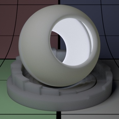
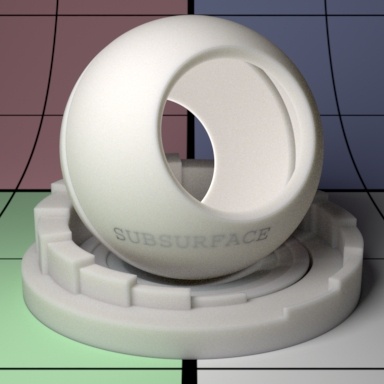
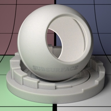
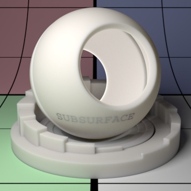
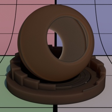
Below left we use "All Hits" and you can plainly see the text "SUBSURFACE" embedded in the sphere. To therightit's set to "Off" which causes the embedded geometry to render incorrectly by clamping that falloff.

Max Continuation Hits
Maximum number of hits to test in all hits mode. This is only valid when Continuation Ray Mode equals All Hits
Follow Topology
Controls how strongly normals are considered in the subsurface computation. This may affect visible details created through bump mapping as well.
Trace Subset
Specify trace subset for inclusion/exclusion when struck by a ray indirectly.
Single Scattering Parameters
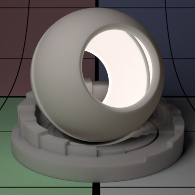
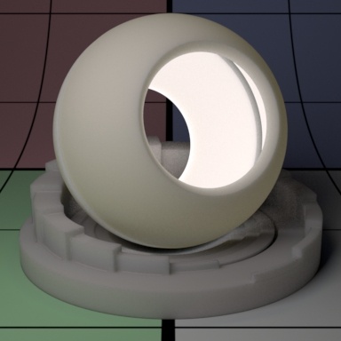
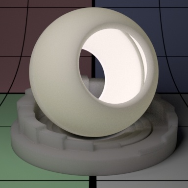
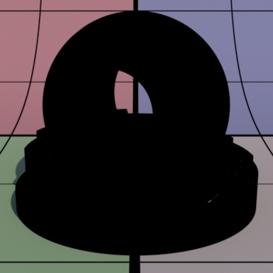
Single scatter is a simple and inexpensive effect for scattering effects. Below a disk light is placed inside the model (for all of these examples) and we render using no diffuse color and again with a default middlegrey diffuse color.
Gain
Single scatter gain or weight.

Color
Single scatter color.
Mean Free Path
Single scattering mean free path scalar distance. This specifies how far the light travels inside an object and as a consequence how smooth the single scattering is. This gets multiplied by the unit length set in the Properties section. Larger values are more translucent.
Mean Free Path Color
How far the light travels in the R, G, and B spectra. This is scaled by Mean Free Path Distance.
Directionality
Single scatter directionality:
0 : isotropic (no effect).
1 : forward scatter which is more light on the backside.
-1: backward scatter which is more light on the front side.


Refractive Index
Single scatter index of refraction. Below are 1.3, 5.0, and then 10.0

Blur
Blur strength for single scatter. This polygonal plane as some text behind it. Increasing the blur causes the text to appear blurrier (and darkens the result some). You may think of this as roughness forscattertransmission.
Backside Direct Illum Gain
Gain for direct illumination from the other side. This increases the influence of backside illumination.


Direction Tint
Tinting color for the Backside Direct Illum Gain. Below uses different colors to tint the result from the first image, which is white.
Double Sided
If on, illuminate on both sides of the surface for this single scatter lobe, that is, this will illuminate the surface whose normal is pointing away from the camera as well.
Trace Control Parameters (Operate similarly to Subsurface Controls Shown in their explanation):
Consider Backside
Whether subsurface respects surfaces on the other side. This is for the hit side, not the illuminating side (which is singlescatterDoubleSided):
- "Off" - It will ignore surfaces on the other side completely. This is useful to make objectsapearthicker than they are.
- "On" - Normal mode, where the diffusion happens between the front and the first surfacebehindit.
Continuation Ray Mode
Control continuation ray mode:
"Off" - Simply trace out of the object (default).
"Last Hit" - Ignore internal geometry and jump to the last surface.
"All Hits" - Scatter (collect light) on all hits as the ray leaves the object. This can bring additional brightness, at the cost of additional noise.
Max Continuation Hits
Maximum numberof hits to test in all hits mode. This is only valid when Continuation Ray Mode equals All Hits
Direct Gain Mode
Control continuation ray mode:
"First Hit" - Simply trace to the next surface (this is tied to considerBackside).
"Last Hit" - Ignore internal geometry and jump to the last surface.
"All Hits" - Scatter (collect light) on all hits as the ray leaves the object. This can bring additional brightness, at the cost of additional noise.
Trace Subset
Specify trace subset for inclusion/exclusion when struck by a ray indirectly.
Scattering Globals
Irradiance Tint
A tint applied to illumination before being scattered by subsurface or single scatter.
Irradiance Roughness
Diffuse roughness to be applied for subsurface or single scatter. A value of 0 represents classic Lambertian shading model. Non-zero values increase the microfacet roughness for the Oren-Nayar shading model. A greater value produces rougher diffuse and may appear slightly darker.
Unit Length
Subsurface and single scatter unit length. It is a multiplier on Mean Free Path Distance. Mean Free Path Distance is often measured in millimeters. If the scene is modeled in some other scale, Unit Length should be set accordingly. The default value of 0.1 is appropriate for scenes modeled in centimeters (the default in Maya) and Mean Free Path Distance measured in millimeters. Small numbers make the object more diffuse (less translucent) while larger numbers increase the scatter effect, making it more translucent.
Glow Parameters
Glow can make an object appear to emit light. This is useful when you need a textured effect like lit panels, circuitry, lava, or other complex effects with local influence in lighting.
This is not an efficient way to light a scene and would require indirect bounces to be at least 2 to be effective. We recommend this as a textured effect and not for actual lighting.
Gain
Glow gain or weight. Below we go from the defaultgreymaterial and increase the gain (using white color) to 0.5 and then 1.0.

Color
Controls the incandescence color, or glow, of the material. Below are various examples of textured inputs to the Color parameter.
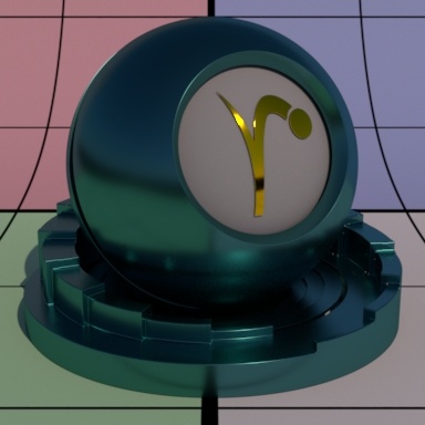
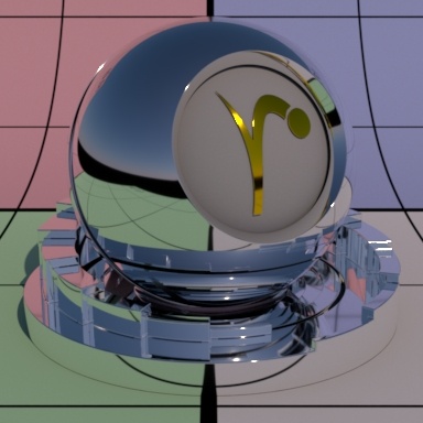
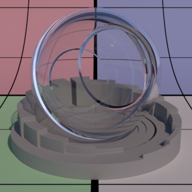
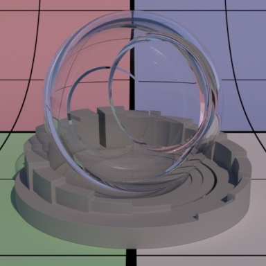
Glass Parameters
Glass parameters are meant to provide a single location for creating and manipulating a physically based glass result. Anything from clear to a colored glass with all levels of roughness and fog in-between are available.

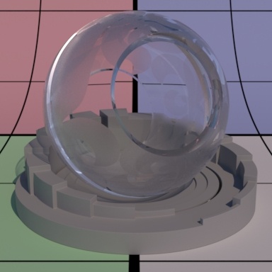
The Refraction and Reflection Gain controls are meant to work together. Using one or the other alone may result in interesting effects but isn't intended by design. Also note that when creatingglassfor the first time, you will find the default gain of 1.0 for Diffuse may interfere with your look. Turn the gain for Diffuse to 0.0 for pure glass.

Refraction Gain
Refraction gain is a multiplier. Lower numbers result in less light making it through the object and might appear as dark tinted glass or simply black at 0.0.

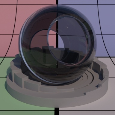
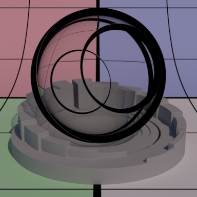
Reflection Gain
Reflection gain is a multiplier. Low numbers decrease the visible reflection result. A setting of 0.0 results in an unrealistic look as seen in the first image below.

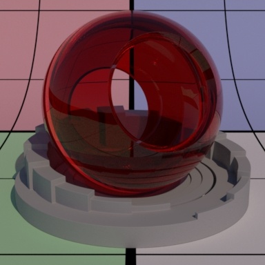
Refraction Color
Refraction color. This allows you to create objects that are realistically colored and have colored shadows just like real transmissive objects (note that Thin Shadows should be enabled on your lights).
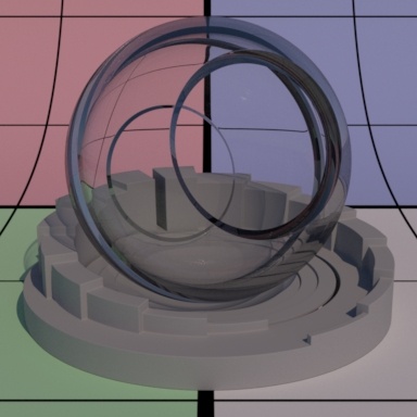
Roughness
Refraction and reflection roughness. Here is where you would simulate frosted or etched glass.


Refractive Index
Index of refraction. The default is 1.5 which is typical of glass. Online resources of Ior values can provide more useful settings. Higher Ior values bend rays more than low values. Use Thin if you want to avoid bending rays.

Enable Manifold Exploration
This sets the glass object to allow exploration for caustic light paths, used with PxrUnified integrator and the options for the Manifold Walk
Manifold Walk IOR
This allows the user to artistically override the refraction index set in the glass lobe for calculating caustic light paths in conjunction with the controls for Manifold Walk found in the PxrUnified integrator.
Thin
If on, correctly split energy according to Refractive Index between reflection and refraction, but do not bend the ray in refraction (simulating a double pane of glass with a single pane or maybe a hollow glass ornament). The below interior parameters are not meant to operate in this mode.

Ignore Accumulate Opacity
This ignores the setting in the integrator to collect alpha values based on glass opacity/refraction.
Blocks Volumes
This setting omits or blocks volumes from rendering when they pass into the interior of the glass object. This also disables the interior settings for the glass lobe. The default is off (left) and on is shown on the right.
Interior Parameters
Single Scatter Albedo
Single scatter albedo color, this creates a fog in the interior of the glass surface. This would be useful for containers of silty or dirty (homogeneous) water. Extinction should not be black or 0. These settings are used/available when Refraction Gain is non-zero.
The Interior Parameters are designed to be convenient for use with PxrPathTracer. When using PxrVCM and Trace Light Paths in lights, for example, this effect will fail to render in the current version.
Extinction
Extinction color. This applies to the above Single Scatter Albedo. It should not be black for Single Scatter Albedo to work. This parameter selects the color that is most effected by extinction or combination of colors. Choosing pure red means red goes extinct but green and blue color combinations do not.
Single Directionality
Controls the directionality of the scattering.
0 : isotropic
1 : forward
-1 : backward
Properties Parameters
This section provide global controls for the entire material. For example, if a Bump is only supplied here, it applies to all the above lobes. Presence is also a global parameter that will mask out or "cutout" all the lobes as-if the object isn't present where the mask has a value of 0.0
Bump
Normal/Bump to use for all lobes unless it is overridden by the individual lobe's bump normal.
Presence
Connect a mask here to apply a cutout pattern to your object. This is useful for cutouts like creating leaves and other thin, complex shapes. It can also be used as opacity for gray values for semi-opaque results when seen directly by the camera.
- This is ignored for non-thin glass refraction and "thick" style objects where color is attenuation through the interior
Presence Cached
Specify whether presence is cached or not. When cached is on, presence will be evaluated per micropolygon as opposed to per shading point when cached is off.
- Since presence computation can be expensive, if there is a heavy shading network such as texturing, then caching is advantageous for better rendering speed though it increases memory.
- Because caching is essentially stored at the tesselation level, if we need finer render details, uncached presence is recommended since it evaluates per shading point.
- There is a trade off between memory and speed. If we have a very simple presence such as a constant value, cached and uncached could be almost equally fast and save some memory. Note that if presence is at constant 1.0 (which is the default), PxrSurface optimizes all of this.
- When subsurface or single scattering is on, to avoid artifacts (related to volume tracking), PxrSurface forces uncached presence internally (ignoring the parameter setting of Presence Cached).
- For similar reasons, PxrSurface ignores presence, cached or not cached, for non-thin glass refraction.
- The intregrator may control the maximum depth at which opacity is not stochastic (noisy)
Shadow Mode
Shadow opacity computation mode:
- Shader and shadow color
- Shadow color only
Shadow Color
Specify shadow color. This parameter is useful for faking a shadow color for art direction purposes. Note that changing the shadow color may impact performance and the result of global illumination.
Utility Pattern
Specify a pattern node for output. For example: One can connect a PxrMatteID to this parameter to output an ID AOV. Or another pattern can be output such as a texture.
Enable Starting Manifold Exploration/Walk
Only available when using the PxrUnified Integrator and the option for Enable Manifold Walk set to ON. This setting should be on for objects intended to catch caustic light paths. Like a diffuse service inside a specular object.
Specular Curvature Clamp
This control is used to override the corresponding integrator setting of Specular Curvature Filter parameter found in PxrVCM and PxrUnified integrators.