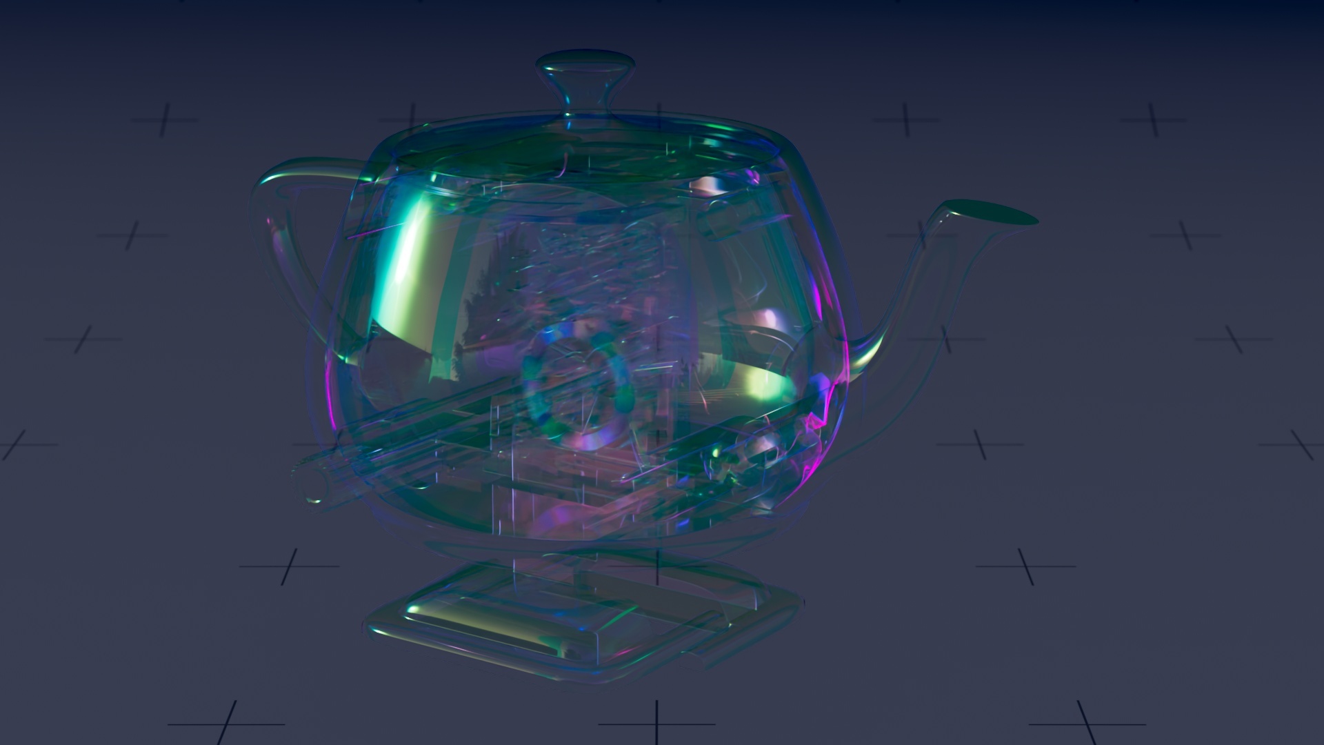

Target Hue
Maps the hues of the colors generated by the underlying physical model to the selected hues.
Incident Angle
Remaps the incident angles before evaluating the iridescence.
Can be used to control the view-dependent colors, e.g. to shift the colors or modify the frequency of the color changes. Should be used with caution as this has an effect on the whole reflectivity and not just the color hues.
Roughness
Micro-facet distribution roughness.
Color Preservation
Can be used to preserve the iridescence colors when high roughness values are set.
This can lead to non-physical material responses, especially at a grazing angle. Values between 0 and 0.5 will gradually increase color preservation at the incident angle while still remaining physically accurate at the grazing angle.
Values between 0.5 and 1 will gradually increase color preservation at the grazing angle while keeping full-color preservation at the incident angle.
Mix
Indicates how pronounced the tail effect should be, ranging linearly from none at all to full tail roughness.
Tail Length
Defines how rough the tail effect should appear, ranging from no roughness change at all to a roughness of 1 (or to 0 with a negative value).
Anisotropy
Defines the amount of anisotropy, changing the co-tangent axis roughness from the original value toward 1 (or toward 0 with a negative anisotropy value).
Anisotropy Direction
Overrides the surface tangent as the anisotropy direction.
Relative Film Thickness
Relative thin film thickness in the range from 0 to 1 will be scaled to the minimum and maximum thickness, respectively.
Min Film Thickness
Minimum thin film thickness in nanometers, driving the iridescent effect.
Max Film Thickness
Maximum thin film thickness in nanometers, driving the iridescent effect.
Film IOR
Thin film index of refraction, driving the iridescent effect.
Pass Iridescence
The iridescence node has two modes of operation.
By default, it works independently and trades physical accuracy for usability by ignoring the material it is layered on.
This option can be turned on if a more physically accurate behavior is desired. In this case, the iridescence computation will be passed to the underlying material, if supported.
Supported materials include dielectrics and conductors. For unsupported materials, the default behavior applies.
Override Exterior IOR
When enabled, the IOR and refracted rays from layers above will be ignored, and the exterior IOR will be set manually.
Exterior IOR
Defines what the IOR of the exterior medium is (can be either the outside medium, eg. air or water, or in the case of a layered material, the top layer medium, like plexiglass or varnish).
Energy Compensation
Indicates how much energy should be added to the lobes, to compensate for the loss inherent to micro-facet models, ranging from no compensation at all to the expected energy from multiple scattering between the micro-facets.
This prevents overly dark results when roughness is high.
Surface Mollification
Defines by how much the roughness can be increased based on local surface curvature. This can help prevent fireflies.
Motion Mollification
Defines by how much the roughness can be increased based on motion blur. This can help prevent fireflies.
Lobe Name
Defines the name that can be used in LPE AOVs for these lobes.
Matte
Defines the name that can be used by the matte system, to output the weight of this lobe in the final material as an AOV.