Contents
In the parameters below, some of them can be overridden by a PxrLayer when connected to the Input Material or through a PxrLayerMixer. PxrLayerSurface is designed to better illustrate which parameters are not able to be overridden in a layer by including only parameters that are global. We recommend this material when you know you will be layering. The results of these settings are unchanged.
- Bold Face parameters are layerable, able to be overridden per layer.
- Italicized parameters are not able to be layered or overridden. These are globally obeyed for all layers. For example: Choosing Burley as a subsurface model will mean all layers will be Burley for that parameter.
Subsurface Scattering Parameters
Note that PxrSurface supports only homogeneous volumes for these models.

Rachael rendered using Path Traced Subsurface Scattering. Image from Blade Runner 2049 © 2017 Alcon Entertainment, LLC.
Courtesy of MPC
Subsurface Model
Select a subsurface scattering model: Jensen Dipole, d'Eon Better Dipole, Burley Normalized, Multiple Mean Free Paths, and Path Traced Modes. The parameters are populated based on the model chosen and are valid for that model. If you change which model you use, your connections may be lost to invalid parameters.
Burley Normalized - produces accurate effects while preserving details. You can find more information on the technical details of this model here .
Jensen and d'Eon Dipoles - are great for very translucent objects like gummies and extended art direction.
Multiple Mean Free Paths - is good for texturing color bleed intuitively. While not necessarily physically correct, its scattering of textured colors works well for art direction while avoiding color shifting.
Path Traced - offers two selections for brute force calculations in subsurface scattering, these provide uncompromising quality and details. The difference between the two is how light falloff is applied.
You may also find this chart helpful in choosing appropriate settings:
| Material | Albedo/Color | Mean Free Path Color |
|---|---|---|
apple | 0.846 0.841 0.528 | 6.96 6.40 1.90 |
| chicken1 | 0.314 0.156 0.126 | 11.61 3.88 1.75 |
| chicken2 | 0.321 0.160 0.108 | 9.44 3.35 1.79 |
| cream | 0.976 0.900 0.725 | 15.03 4.66 2.54 |
| ketchup | 0.164 0.006 0.002 | 4.76 0.58 0.39 |
| marble | 0.830 0.791 0.753 | 8.51 5.57 3.95 |
| potato | 0.764 0.613 0.213 | 14.27 7.23 2.04 |
| skim milk | 0.815 0.813 0.682 | 18.42 10.44 3.50 |
| skin1 | 0.436 0.227 0.131 | 3.67 1.37 0.68 |
| skin2 | 0.623 0.433 0.343 | 4.82 1.69 1.09 |
| whole milk | 0.908 0.881 0.759 | 10.90 6.58 2.51 |
Gain
Subsurface scattering weight. Higher numbers increase the visibility of the subsurface scattering.

Color
Subsurface scattering color.
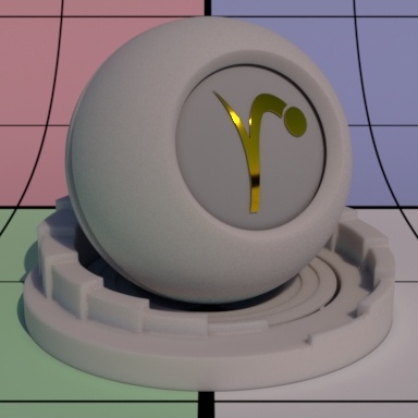
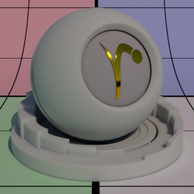
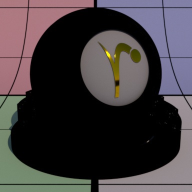
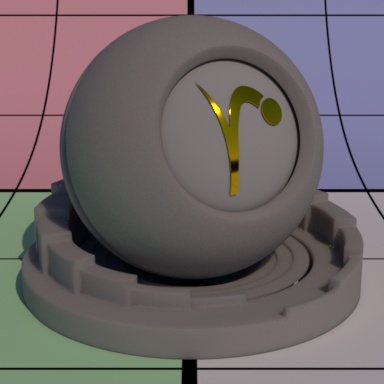
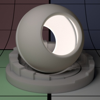
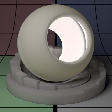
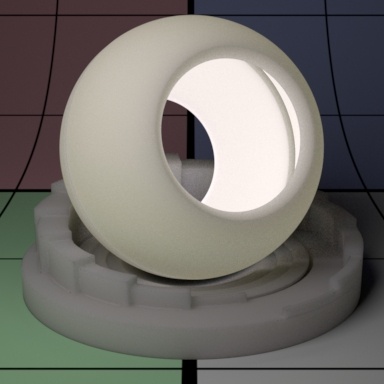
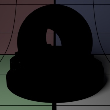
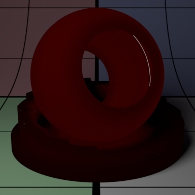
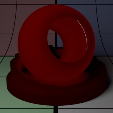
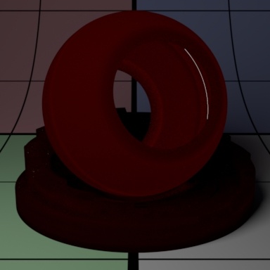
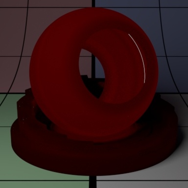
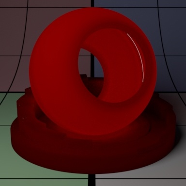
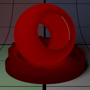
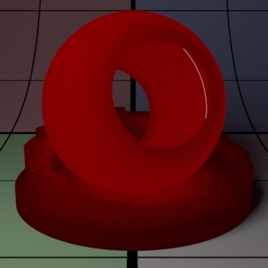
Mean Free Path Distance
Subsurface scattering mean free path distance (mfpd). This specifies how far the light travels inside an object and as a consequence how smooth the subsurface scattering is. This gets multiplied by the unit length set in the Properties section. Higher amounts make the object appear less opaque and more translucent as well as increase noise. Small amounts make the surface look diffuse and it may be more efficient to turn off the effect (0.0 Gain) if it's not visually important. Below we change the values from 8 to 16 and then 32. Notice how the sphere and pedestal become "softer" and more translucent. Your render times might also increase at high values due to noise generated by translucent objects. Noter that high or physically implausible values may generate more noise or even fireflies in some modes.
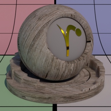
Mean Free Path Color
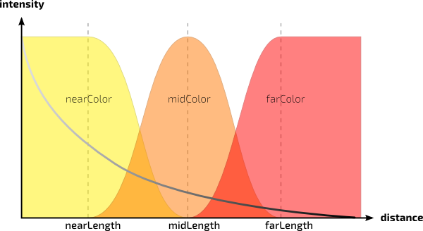
How far the light travels in the Red, Green, and Blue spectra. This is scaled by Mean Free Path Distance. Different colors may spread more or less and provide interesting effects like the red color bleeding into shadow edges on skin. The RGB values correspond to how far the light travels in that color band. For example, and RGB value of 0.8 0.65 0.5 means Red spreads furthest at 0.8, then Green and finally Blue traveling the least distance in the object scatter result. Below we've taken out the center sphere and replaced it with a bright disk light at the back of the outer sphere. Note that the sphere and pedestal share the same material and lighting plays an important role in your result.
Post Tint
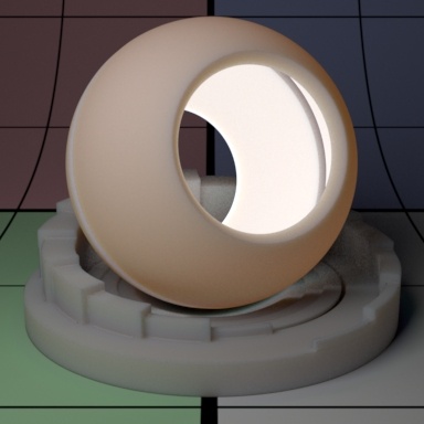
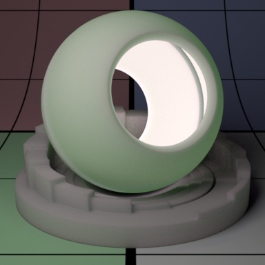
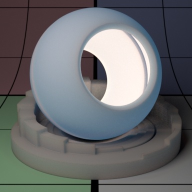
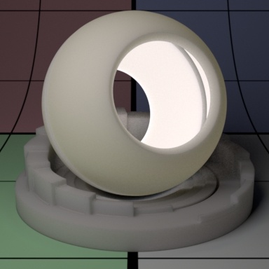
Tint that is applied at the end of the subsurface computation. Below on the left is a normal render and on the right, a very light blue tint is added. If we want to apply the tint before the subsurface computation, set Irradiance Tint in the Properties section.
Path Traced (Exponential and Non-Exponential)
This method provides an accurate and robust light transport solution to produce scattering. This technique works well with thin geometry and edges, replacing times where you might need to combine Single and Subsurface Scattering. Note that too-large Mean Free Path settings may cause fireflies or bright spots in the resulting render.
Below you see them compared, notice the Non-Exponential is brighter as light carried further into the object (examine the lower right of the spheroid model).


Directionality
This control scatters light anisotropically, that is, it can travel in one direction (forward or backwards toward the light) more than the opposite direction. In this case the light travels forward (from the light) the higher you increase the setting. Below the corners become more pronounced and the internal Subsurface geometry becomes harder to see.

Bleed
Increasing this allows the light to travel further, increasing the subsurface effect, without losing details which is typically a side effect of increasing the Diffuse Mean Free Path.
Resolve Self Intersections
If your surface has self-intersections, imagine a sock-mouth where the interior and tongue may be the same surface, only the outside is considered for subsurface scattering.
Internal Reflection Index
If you find you have some bright or "glowing" corners, you can decrease this parameter to lessen the effect. From left to right you'll notice the corners become softer and less obvious. This parameter may also be used to reduce fireflies when increased (1.0 is a soft upper limit). This may reduce the energy artificially and should be handled with care. Some over-bright areas may be caused by a large or physically incorrect Mean Free Path Distance and should be reduced rather than using this control as a first solution.


Diffuse Blend
Increasing this parameter reduces the effect of the scattering itself by blending more with a diffuse response. Notice the corners below become more "solid" looking as does the whole object.

Multiple Mean Free Paths Description
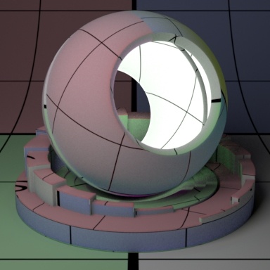
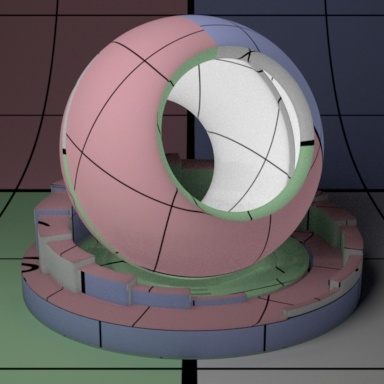
Multiple Mean Free Paths operates differently than the others in a few significant ways. For most cases, you will be happy with the results of the other models. However, there are instances where the user may want a non-physical way to control the colors of the scattering. The Mean Free Path Color in many models uses the supplied RGB value to determine the color scatter as noted in the parameter description. This means your result may have color shifts that are not desirable. Let's say you supply a textured color of RGB 0.51 0.28 0.31 which is a pink color. The scattering result will also include the green (0.28) and blue (0.31) responses. The Multiple Mean Free Paths model maintains the pink color. Below is an example using this scenario illustrating the differences. The texture is connected to the Color and Mean Free Path Color of the Jensen Dipole and to the Short and Long Colors of the Multiple Mean Free Paths model in addition. Note the color shift on the Jensen model (Left) while the Multiple Mean Free Paths version maintains the colors of the texture at all depths where connected.
Short Gain
Short subsurface gain or weight. This is only valid for Multiple Mean Free Paths subsurface model.
Short Color
Short subsurface color. This is only valid for Multiple Mean Free Paths subsurface model. Above uses Red as the chosen color.
Long Gain
Long subsurface gain or weight. This is only valid for Multiple Mean Free Paths subsurface model. Operates the same as Short Gain.
Long Color
Long subsurface color. This is only valid for Multiple Mean Free Paths subsurface model. Operates the same as Short Color.
Short MFP Distance
Short subsurfacemeanfree path scalar distance. Below we go from 16 to 24 and finally 32.

Long MFP Distance
Short subsurface meanfree path scalar distance. Below we go from 16 to 24 and finally 32.
Diffuse Computation Switch
When non-zero, it allows subsurface scattering to be approximated by simple diffuse reflection when the dmfp is shorter than the ray footprint. This gives faster rendering time and less noise -- typically on distant objects where the subsurface scattering is short relative to the size of a pixel. The default is 0 (off). Avoid using this parameter with the Path Traced options.
Double Sided
If on, illuminate on both sides of the surface for this subsurface lobe, that is, this will illuminate the surface whose normal is pointing away from the camera as well. If not on, it will not render on the backside.
Transmit Gain
This only applies when Double Sided is on. Instead of using the Subsurface Gain for controlling the intensity of the subsurface transmission, we use the Transmit Gain. If it's 0.0, then the effect is off.
Trace Control:
Consider Backside
Whether subsurface respects surfaces on the other side. This is for the hit side, not the illuminating side (which is subsurfaceDoubleSided):
- "Off" - It will ignore surfaces on the other side completely. This is useful to make objects appear thicker than they are.
- "On" - Normal mode, where the diffusion happens between the front and the first surfacebehindit.
Continuation Ray Mode
This is useful when the user requires scattering to contribute between different objects as well as within an object that may be modeled with a void or space in the interior such as a mouth that is part of the same mesh as the face.
Control continuation ray mode:
"Off" - Simply trace out of the object (default).
"Last Hit" - Ignore internal geometry and jump to the last surface.
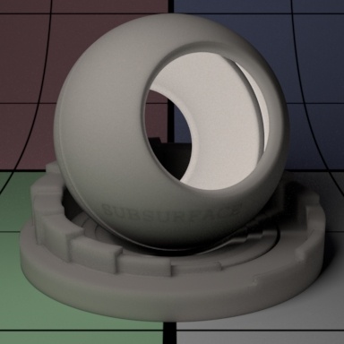
"All Hits" - Scatter (collect light) on all hits as the ray leaves the object. This can bring additional brightness, at the cost of additional noise.
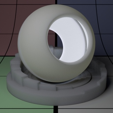
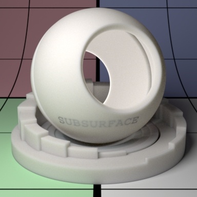
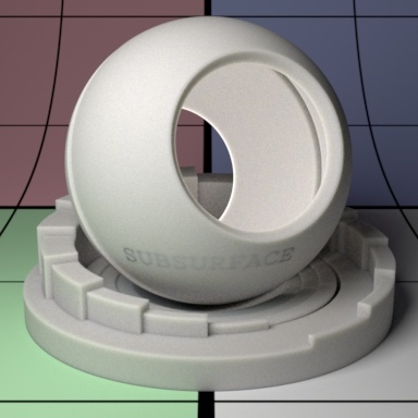
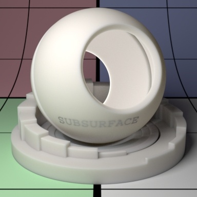
Below left we use "All Hits" and you can plainly see the text "SUBSURFACE" embedded in the sphere. To therightit's set to "Off" which causes the embedded geometry to render incorrectly by clamping that falloff.

Max Continuation Hits
Maximum number of hits to test in all hits mode. This is only valid when Continuation Ray Mode equals All Hits
Follow Topology
Controls how strongly normals are considered in the subsurface computation. This may affect visible details created through bump mapping as well.
Trace Subset
Specify trace subset for inclusion/exclusion when struck by a ray indirectly.