Contents
This pattern layers the input vector displacement patterns.
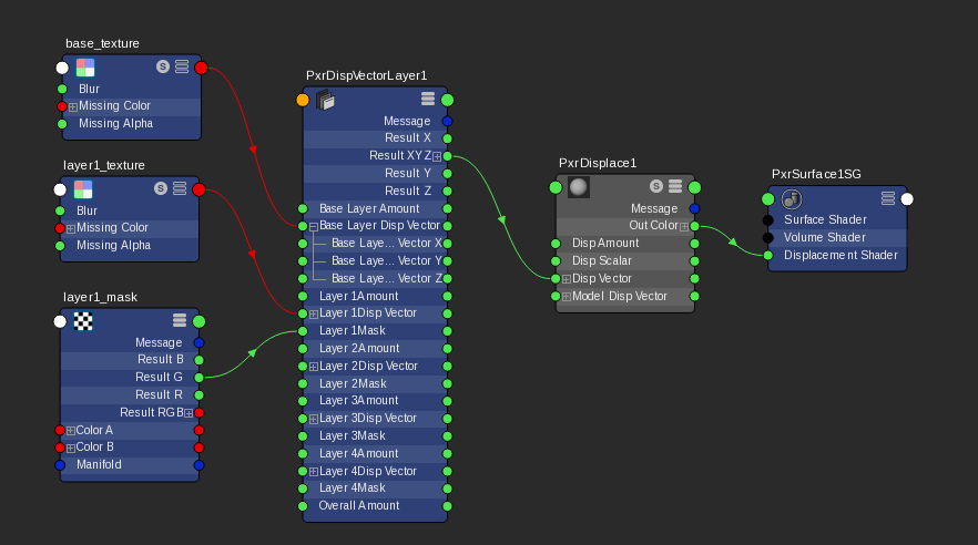
Each PxrDispVectorLayer supports up to 5 layers. To use more than 5 layers, we could connect the result of one PxrDispVectorLayer node to the input of another PxrDispVectorLayer node.
If you need more than 5 layers, connect the result of one PxrDispVectorLayer node to the input of another PxrDispVectorLayer node.
We need to connect the result to the input of PxrDisplace's Vector Displacement in order to displace the geometry.
Input Parameters
Overall Gain
Controls the gain of the final layered vector displacement result. This is handy when we want to globally adjust the amount of all layered displacement values. Each layer's gain is being multiplied by this parameter.
Base Layer
Enabled
By default, the base layer is enabled. But say we need to debug, we can disable the base layer by unchecking this parameter. It if is unchecked, the base layer will be skipped for layering.
Base Layer Gain
Gain for the base layer.
Base Layer Vector
Connection to the vector displacement pattern. It can be any pattern's output a vector or color result such as resultXYZ or resultRGB.
Layer1
Enabled
If checked, layer 1 is enabled.
Layer 1 Gain
Gain for the layer 1.
Layer 1 Vector
Connection to the vector displacement. It can be any pattern's output a vector or color result such as resultXYZ or resultRGB.
Layer 1 Mask
Mask for this layer 1. Values closer to zero will apply less of this layer.
Layer 1 Operation
Choose how this layer's displacement combines with the base layer.
- 1: Add - adds each vector component of layer 1 to the base layer.
- 2: Over - composites each vector component of layer 1 on top of the base layer.
- 3: Multiply - multiplies each vector component of layer 1 with the base layer.
- 4: Average - returns the average of each vector component between layer 1 and the base layer.
- 5: Min - returns the minimum of each vector component between layer 1 and the base layer.
- 6: Max - returns the maximum of each vector component between layer 1 and the base layer.
Layer2
Enabled
If checked, layer 2 is enabled.
Layer 2 Gain
Gain for the layer 2.
Layer 2 Vector
Connection to the vector displacement. It can be any patterns that output a vector or color result such as resultXYZ or resultRGB.
Layer 2 Mask
Mask for this layer 2. Values closer to zero will apply less of this layer.
Layer 2 Operation
Choose how this layer's displacement combines with the previous layer. If the layer 1 is not enabled, it will combine with the result of the base layer.
- 1: Add - adds each vector component of layer 2 to layer 1.
- 2: Over - composites each vector component of layer 2 on top of layer 1.
- 3: Multiply - multiplies each vector component of layer 2 with layer 1.
- 4: Average - returns the averageeach vector component of between layer 2 and layer 1.
- 5: Min - returns the minimum each vector component ofbetween layer 2 and layer 1.
- 6: Max - returns the maximum each vector component of between layer 2 and layer 1.
Layer 3 to 4
Similar parameters to Layer 2.
Output Parameters
resultXYZ
The vector result.
resultX
The X component from the resultXYZ output.
resultY
The Y component from the resultXYZ output.
resultZ
The Z component from the resultXYZ output.